Limb limiting structure facilitating CT diagnosis
A technology of limiting structure and limbs, which is applied in patient positioning for diagnosis, computerized tomography scanner, echo tomography, etc., can solve the problems of poor adjustment accuracy, difficulty in adjusting the fixed limit angle, poor applicability, etc., to achieve Effects of improving accuracy, reducing local maintenance costs, and reducing burden
- Summary
- Abstract
- Description
- Claims
- Application Information
AI Technical Summary
Problems solved by technology
Method used
Image
Examples
Embodiment 1
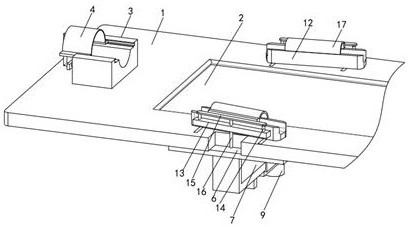
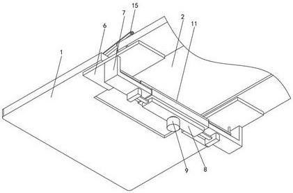
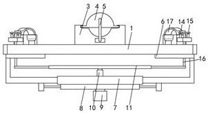
[0030] like Figure 1-3 As shown in the figure, a limb limiting structure that is convenient for CT diagnosis proposed by the present invention includes a bed board 1, a rope net 2 and a head pillow 3. The movable plate 6, the top of the movable plate 6 is provided with a limit seat 12, the side wall of the limit seat 12 is fixedly connected with a fixed plate 13, the top of the fixed plate 13 is symmetrically provided with a telescopic rod two 14, the top of the telescopic rod two 14 A connecting plate 15 is fixedly connected, a gusset mechanism 17 is fixedly connected to the side wall of the connecting plate 15, and an adjusting rod 16 is arranged at the bottom of the connecting plate 15, and a telescopic bracket 7 is fixedly connected between the symmetrical movable plates 6, and the telescopic bracket 7 An adjusting mechanism 8 is fixedly connected to the bottom of the adjusting mechanism 8, a motor 9 is installed on the bottom outer wall of the adjusting mechanism 8, and ...
Embodiment 2
[0033] like Figure 2-4 As shown in the figure, the present invention proposes a limb limiting structure that is convenient for CT diagnosis. Compared with the first embodiment, this embodiment further includes: an opening is provided on the middle shell wall of the bed board 1, and the rope net 2 is installed in the opening, The headrest block 3 is arranged on the top of the bed board 1, and the headrest block 3 is located on the left side of the rope net 2. The headrest block 3 is slidably connected with a head cover 4, and the interior of the head cover 4 is provided with a through groove to pass through. A movable frame 5 is movably connected in the groove, and the end of the movable frame 5 away from the through slot is fixedly connected to the head cover 4. The movable frame 5 is sleeved with a return spring and a stopper, and the return spring is fixedly connected with one side away from the stopper. On the left outer wall of the headrest block 3, the two sides of the r...
Embodiment 3
[0036] like Figure 5 , Image 6 and Figure 7 As shown in the figure, the present invention proposes a limb limiting structure that is convenient for CT diagnosis. Compared with Embodiment 1 or Embodiment 2, this embodiment further includes: the adjustment mechanism 8 includes a casing disposed on the outer wall of the bottom of the telescopic support 7 81. The output end of the motor 9 passes through the bottom shell wall of the housing 81, and is equipped with a swing rod 82. The two ends of the swing rod 82 are movably connected with a strut 83, and one end of the strut 83 away from the swing rod 82 is hinged with a sliding plate two. 84. A connecting rod 85 is welded to one end of the second slide plate 84 away from the strut 83, and one end of the connecting rod 85 away from the second slide plate 84 passes through the side wall of the housing 81 and is fixedly connected to the telescopic bracket 7. The gusset mechanism 17 includes a set of The arc-shaped gusset plate ...
PUM
 Abstract
Description
Claims
Application Information
 - R&D
- Intellectual Property
- Life Sciences
- Materials
- Tech Scout
- Unparalleled Data Quality
- Higher Quality Content
- 60% Fewer Hallucinations
Browse by: Latest US Patents, China's latest patents, Technical Efficacy Thesaurus, Application Domain, Technology Topic, Popular Technical Reports.
© 2025 PatSnap. All rights reserved.Legal|Privacy policy|Modern Slavery Act Transparency Statement|Sitemap|About US| Contact US: help@patsnap.com


