
Debridement skin grafting device for burn patients

A patient and skin grafting technology, applied in the field of medical devices, can solve the problems of cumbersome operation steps and inconvenient use by doctors, and achieve the effect of simple operation, low clinical experience requirements, and convenient use

Pending Publication Date: 2022-08-09
赵孝开
View PDF0 Cites 0 Cited by
  • Summary
  • Abstract
  • Description
  • Claims
  • Application Information

AI Technical Summary

Problems solved by technology

[0004] When the existing drum-type skin removal machine is used for skin removal, medical personnel need to wipe the drum surface clean and adjust the knife holder to a suitable thickness for skin removal, and then apply glue on the drum surface and the skin to a suitable skin removal shape. After the glue dries slightly, the operator holds the handle of the drum with the left hand and the handle of the knife with the right hand. After aligning the front edge of the drum with the glued area of ​​the skin donor area, press to make the drum face contact with the skin, and roll the drum face backward. At the same time, do a sawing action with your right hand to remove the skin. However, if you find that the skin on one side is wider during the skin removal process, you need to slightly lift the drum surface on the wider side. If the skin on one side is narrower It is necessary to press down on the side of the drum to adjust the width of the skin, which requires coordinated movements of the left and right hands, and requires a high level of clinical experience for the doctor. The skin after excision may need to be partially trimmed before it can be used. The operation steps are cumbersome and inconvenient for the doctor. For this purpose, we propose a debridement and skin grafting device for burn patients

Method used


Image

  • Debridement skin grafting device for burn patients
  • Debridement skin grafting device for burn patients
  • Debridement skin grafting device for burn patients

Examples


Embodiment Construction

[0035] The technical solutions in the embodiments of the present invention will be clearly and completely described below with reference to the accompanying drawings in the embodiments of the present invention. Obviously, the described embodiments are only a part of the embodiments of the present invention, but not all of the embodiments. Based on the embodiments of the present invention, all other embodiments obtained by those of ordinary skill in the art without creative efforts shall fall within the protection scope of the present invention.

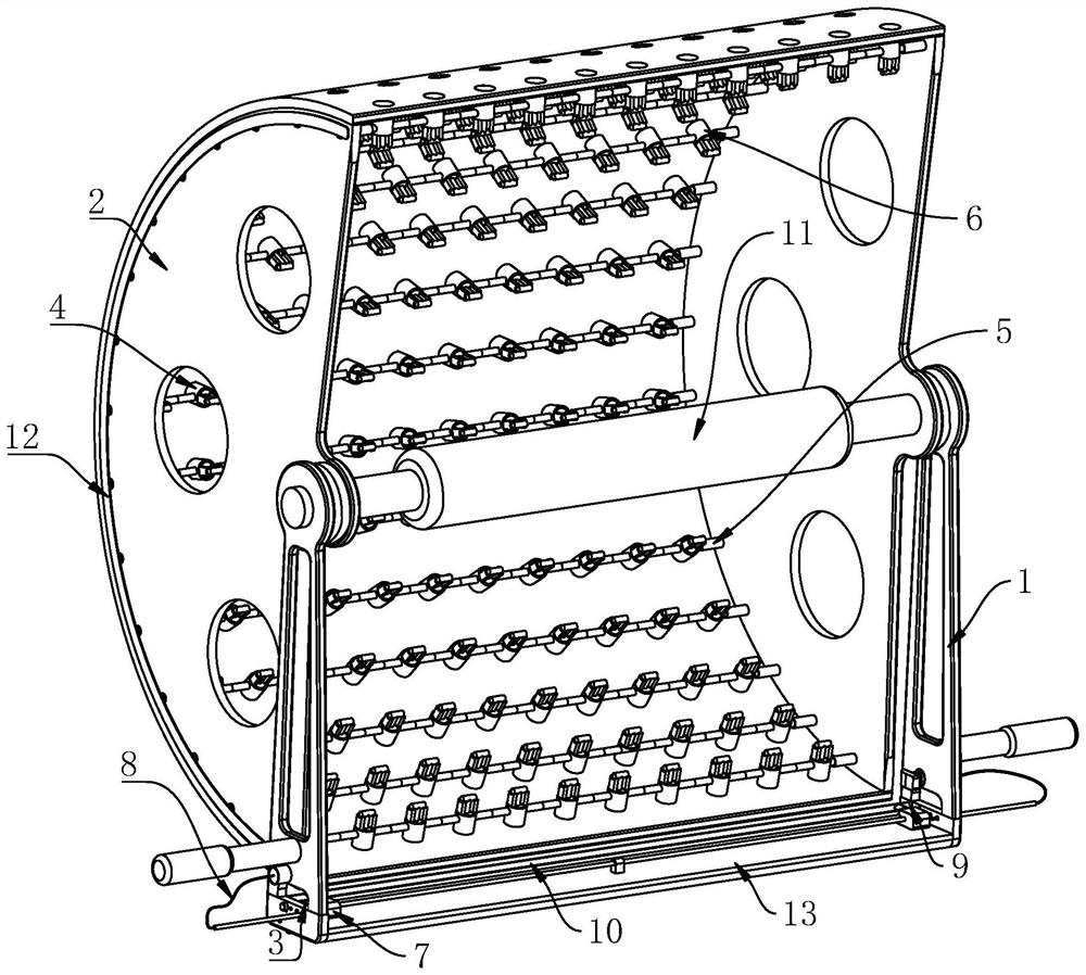
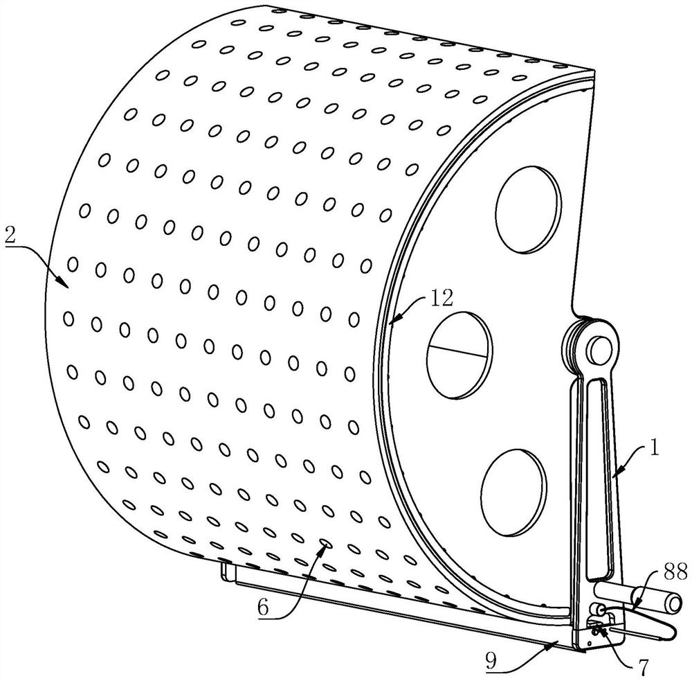
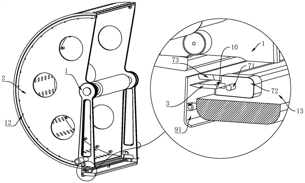
[0036] see Figure 1-8 , the present invention provides a technical solution: Embodiment 1, a debridement and skin grafting device for burn patients, comprising:

[0037] Bracket 1, the bracket 1 can be placed on the surface of the skin of the patient to be taken, and both sides of the bracket 1 are fixedly connected with handles, and the bracket 1 supports the patient's skin surface and slides relatively;

[0038] Roller 2, the roll...


PUM


Abstract

The invention discloses a burn patient debridement skin grafting device, which comprises a rotating roller, a support and a skin grafting device, the rotating roller is arranged in the support, and the rotating roller rotates relative to the support; the blade is installed in the support through a tool apron, and the blade cuts the surface of the skin after the rotating roller adsorbs the skin; the adsorption mechanism comprises a plurality of adsorption units which are transversely distributed, the multiple adsorption units are adsorbed to the skin surface of the patient, each adsorption unit can adsorb the skin surface of the patient, and the multiple adsorption units are connected through elastic strips; the number of the side cutting mechanisms is two, and the two side cutting mechanisms are symmetrically installed on the two sides of the support; a medical worker only needs to adjust the adsorption mechanism to be in the shape for adsorbing the skin of a patient before skin taking, a doctor only needs to operate with two hands at the same time, the requirement for clinical experience of the doctor is low, the possibility that the skin is excessively trimmed after the skin is taken down is reduced, operation is easy, and the doctor can conveniently use the skin taking device.

Description

technical field [0001] The invention relates to the technical field of medical devices, in particular to a debridement and skin grafting device for burn patients. Background technique [0002] Skin grafting is a cosmetic surgery for skin problems. Generally, a part of the skin is removed from the healthy skin to cover the area where the scar has been excised. After the operation, there will be suture marks around the wound, and there will be scars on the site where the skin is taken. If you choose a skin graft that is very close to the skin, plus the suture technique is good and the skin survives, the effect will be much better than the previous scars. Skin grafting surgery It is mainly suitable for scars left by scalds, burns and other conditions. [0003] After the burn, the patient needs to first debride the skin surface, that is, use surgical instruments such as a dermatome, a sharp-blade curette, etc. to completely remove the necrotic tissue at the wound, and then use ...

Claims


Application Information

Patent Timeline
Patent Type & Authority Applications(China)
IPC IPC(8): A61B17/322
CPCA61B17/322
Inventor 赵孝开
Owner 赵孝开
Learn More