Water treatment method

A water treatment and outlet pipe technology, applied in the field of water treatment, can solve the problems of inability to refine sewage or water purification treatment, inconvenient movement, high labor cost, etc., and achieve the effect of ingenious design concept, convenient later maintenance, and high degree of automation

Pending Publication Date: 2022-08-09
陈志伟
View PDF0 Cites 0 Cited by
  • Summary
  • Abstract
  • Description
  • Claims
  • Application Information

AI Technical Summary

Problems solved by technology

[0004] The sedimentation tank requires a large area and a large amount of engineering;
[0005] (2) The process is extensive and inefficient;
[0006] Manual management is adopted to specifically manage how to enter water, how to inject chemicals, how to drain water, and how to discharge waste, etc. The operation is complex and belongs to extensive management, and it is impossible to refine sewage or water purification;
[0007] (3) High cost
[0008] High equipment cost, high labor cost, large investment, inconvenient to move, poor flexibility

Method used


Image

  • Water treatment method
  • Water treatment method
  • Water treatment method

Examples


Embodiment 1

[0085] Example 1: Smart water treatment scheme with rotating filter element (preferred scheme)

[0086] (1) Intelligent water treatment device with rotating filter element

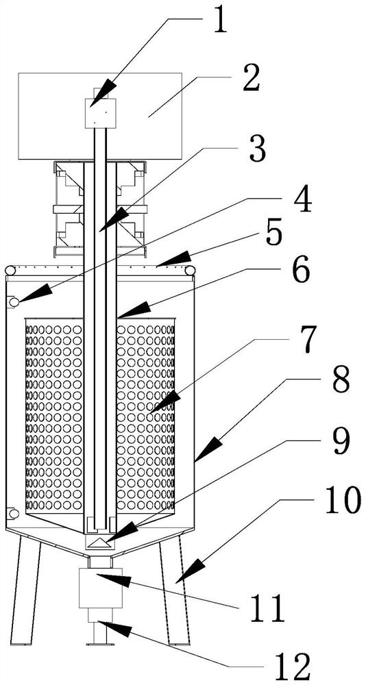
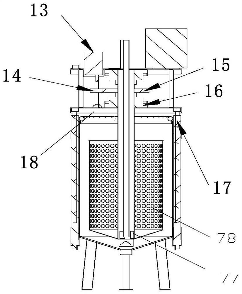
[0087] like Figure 1-4 , an intelligent water treatment device with a rotating filter element, including a container (specifically, an outer barrel 8, and the container can also be a sedimentation tank. At this time, there is no need for feet at the bottom of the sedimentation tank, and the bottom of the sedimentation tank can be connected to a discharge mechanism), a filter element 7. The filter element lifting mechanism, the liquid inlet pipe (5), the dosing mechanism, the liquid pumping mechanism and the discharging mechanism;

[0088] The filter element is placed in the container; the barrel wall of the filter element is provided with a plurality of filter holes;

[0089] The filter element is a rotary filter element; the filter element lifting mechanism includes a lifting platform and an electronic...

Embodiment 2

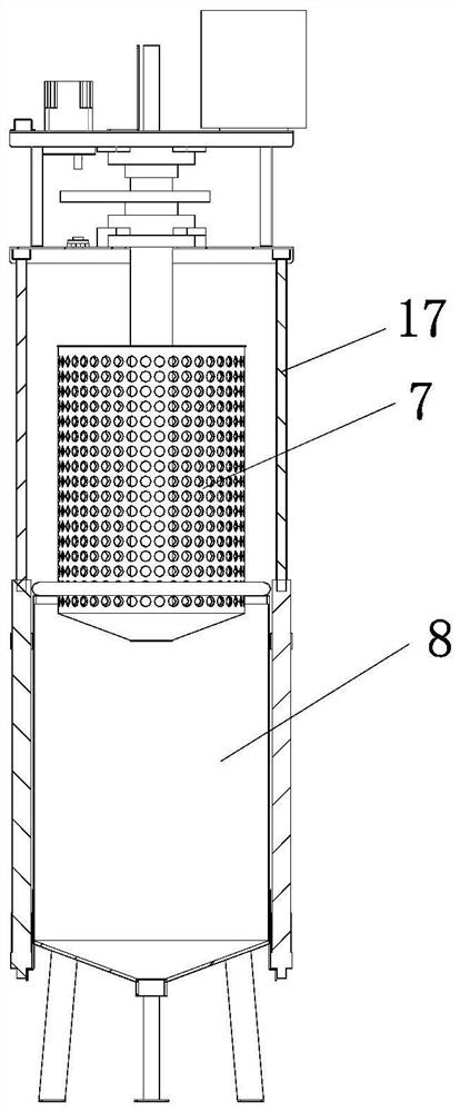
[0208] Example 2: Smart Water Treatment Scheme with Non-Rotating Filter Cartridges (Second-Optimal Scheme)

[0209] see Figure 18-20 , an intelligent water treatment device, including a container, a filter element 7, a filter element lifting mechanism, a liquid inlet pipe 5, a liquid pumping mechanism and a discharging mechanism;

[0210] The filter element is placed in the container; the filter element is a barrel-type device, and the barrel wall of the filter element is provided with a plurality of filter holes;

[0211] The filter element lifting mechanism includes a lifting platform and an electronically controlled lifting driving mechanism used to drive the lifting platform for lifting movement; the filter element is fixed on the lifting platform; looseness

[0212] The liquid inlet pipe is fixed in the container; the liquid inlet pipe is used to introduce the water to be purified and the water treatment agent into the container, and the water supply pipeline of the li...


PUM


Abstract

The invention discloses a water treatment method. The method comprises the following steps: 1, feeding liquid; the electric control lifting driving mechanism is started by the controller to lift the filter element, so that water to be treated enters the container and is ejected from the water inlet pipe to wash the outer wall of the filter element, and the self-cleaning of the filter element is realized; step 2, a reaction step; after the liquid in the container reaches a certain set liquid level, stopping feeding the liquid, and waiting for a preset time, so that the purifying medicine in the solution fully plays a role; step 3, a water pumping step; the controller drives the filter element to descend through the electric control lifting driving mechanism, after the filter element descends to a preset height to ensure that the lower end of the water outlet pipe is in contact with the liquid level, the water suction pump is started, and treated water in the filter element is sucked through the water suction pipe; 4, discharging waste materials; after the sediment is discharged, the discharging pipe is closed again; the circulating water treatment can be realized, and the water treatment efficiency is high.

Description

technical field [0001] The present invention relates to a water treatment method. Background technique [0002] The existing water treatment methods generally use one-stage or multi-stage sedimentation tanks, which have the following shortcomings: [0003] (1) covers a large area; [0004] The sedimentation tank requires a large area and a large amount of engineering; [0005] (2) The process is extensive and the efficiency is low; [0006] Manual management is adopted to specifically manage how to enter water, how to administer medicine, how to drain water, how to discharge waste, etc. The operation is complicated and belongs to extensive management, which cannot be refined for sewage or water purification; [0007] (3) High cost [0008] The equipment cost is high, the labor cost is high, the investment is large, it is inconvenient to move, and the flexibility is poor. [0009] Therefore, it is necessary to design a new water treatment method. SUMMARY OF THE INVENTI...

Claims


Application Information

Patent Timeline
Patent Type & Authority Applications(China)
IPC IPC(8): C02F9/04C02F11/125
CPCC02F1/5281C02F1/001C02F11/125C02F2001/007
Inventor 陈志伟赵钢
Owner 陈志伟
Why Eureka
Try Eureka