
Rock breaking method, rock breaking device and tunneling device

A rock-breaking device and rock-breaking technology, applied in the field of rock-breaking devices, tunneling devices, and rock-breaking methods, can solve the problems of maximization, limited number of cutter heads, and not improving the cutting efficiency of a single cutter head, so as to avoid bearing bending moment Effect

Pending Publication Date: 2022-08-09
CHINA RAILWAY ENGINEERING EQUIPMENT GROUP CO LTD
View PDF3 Cites 0 Cited by
  • Summary
  • Abstract
  • Description
  • Claims
  • Application Information

AI Technical Summary

Problems solved by technology

[0008] Through the above analysis, it can be seen that in the composite cutting type hard rock roadheader cutter head disclosed by the patent application CN108571326A and the guide hole reaming rotary cutting TBM cutter head disclosed by the patent application CN21400715U, the driving load of the cutter, that is, the The jacking force provided by the disk is inconsistent with the direction of the rock-breaking part (blade) of the cutter, and the included angle is usually too large, which cannot maximize the rock-breaking efficiency of the cutter. A bending moment is generated at the place, and it is easy to cause chipping
[0009] Publication No. CN108868811A discloses a roadheader hard rock cutting device and a patent application CN208619111U discloses a multi-arm cantilever roadheader equipped with a suspension cutter to break rock through the swing of the cantilever to drive the cutter into the rock. The driving load can be aligned with the action direction of the blade, but the relative angle between the blade and the rock is fixed, which cannot effectively create a free surface and ensure continuous and efficient excavation
In addition, the cantilever structure is bulky and heavy, and the number of cutter heads that can be arranged is limited. It is still difficult to effectively improve the construction efficiency without improving the cutting efficiency of a single cutter head

Method used


Image

  • Rock breaking method, rock breaking device and tunneling device
  • Rock breaking method, rock breaking device and tunneling device
  • Rock breaking method, rock breaking device and tunneling device

Examples


Embodiment 1

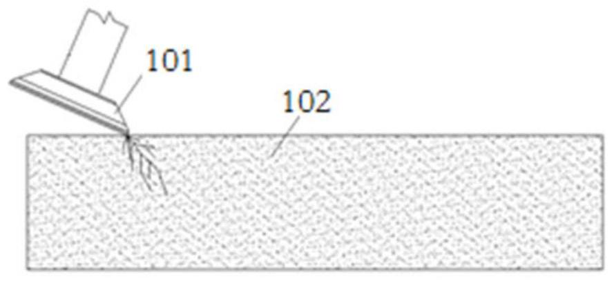
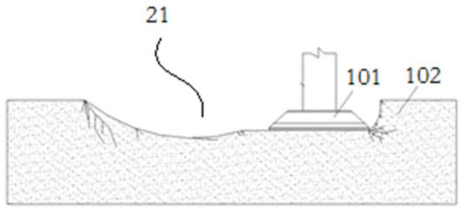
[0063] The rock breaking method includes the following steps: 1) use the hob 101 with its own hob drive device to beveled into the excavation surface 102 (such as figure 1 , Figure 4 ), and move the hob 101 along the set path until the cutting groove 21 that can be entered by the hob 101 as a whole (eg figure 2 , Figure 4 ); 2) Adjust the posture of the hob 101 so that the hob 101 and the excavation surface are substantially parallel (eg figure 2 ), move the hob 101 to make a flat cut towards the groove wall of the groove 21 until the excavation of the excavation surface is completed (eg Figure 5 , Figure 9 , Figure 10-Figure 15 ).

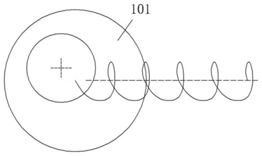
[0064] In this embodiment, the rotation axis of the hob 101 is eccentrically arranged to achieve the effect of vibrating rock breaking (such as image 3 ). In addition, in order to realize the adjustment of the inclination angle between the hob 101 and the excavation face, the hob 101 is mounted on a swing arm 103 (such as Image 6 ...

Embodiment 2

[0067] In Embodiment 1 of the rock breaking method of the present invention, the same hob 101 is used in step 1) and step 2). In this embodiment, the hob in step 2) can be a replaced hob For example, the roadheader has two cutting arms, the hob in step 1) is located on one of the cutting arms, and the hob in step 2) is located on the other cutting arm.

Embodiment 3

[0069] In Embodiments 1 and 2 of the rock breaking method of the present invention, one hob 101 is used to excavate the excavation face. In this embodiment, three hob 101 are used to excavate at the same time, among which three The hob cutters are located at different positions on the excavation surface, for example, in the radial direction of the central spindle 105, and the distances between the hob cutters 101 and the central spindle 105 are not equal. Of course, in other embodiments, the number of each hob may be two, or more than four, and the number of the hob may be selected according to specific conditions.


PUM


Abstract

The invention relates to full-section tunneling equipment for a soil layer or a rock layer, in particular to a rock breaking method, a rock breaking device and a tunneling device. The rock breaking method comprises the following steps that (1) a cutting edge of a hobbing cutter with a hobbing cutter driving device is used for obliquely cutting into rock, and the hobbing cutter is moved until a cutting groove allowing the whole hobbing cutter to enter is excavated in an excavation face; and (2) the posture of the hob is adjusted, or the hob is replaced, so that the cutting edge of the hob flatly cuts the groove wall of the cutting groove, and the hob is horizontally moved until excavation of the excavation face is completed. In the step 1) and the step 2), the cutting edge direction of the hob and the driving load are basically located in the same direction. Therefore, the cutting edge can be prevented from bearing bending moment, tipping is reduced, the normal working period of the cutter is prolonged, and the shutdown frequency is reduced. In conclusion, according to the rock breaking method, the characteristic that the tensile-shear strength of the rock is lower than the compressive strength can be fully utilized, tensile-shear damage of the hard rock is achieved, the rock breaking efficiency is improved, and meanwhile the loss of the rock breaking device is reduced.

Description

technical field [0001] The invention relates to full-section excavation equipment for soil layers or rock layers, in particular to a rock-breaking method, a rock-breaking device and an excavation device. Background technique [0002] Nowadays, the application of full-section excavation equipment has become very popular in tunnel and flat tunnel excavation construction. The traditional typical full-section roadheading equipment includes the main machine of the roadheader and the supporting equipment. The main machine of the roadheader includes a shield body, a cutter head and a main drive. The cutter head includes a cutter head panel and a cutter set on the cutter head panel. When excavating in a rock layer, the rock-breaking cutter mainly uses a hob, and the roller of the hob is used. The extension direction is parallel to the face (excavation face), and the blade of the hob is perpendicular to the face. During the excavation process, the main engine of the roadheader driv...

Claims


Application Information

Patent Timeline
Patent Type & Authority Applications(China)
IPC IPC(8): E21D9/11E21D9/10
CPCE21D9/11E21D9/1086E21D9/1093
Inventor 白中坤毕程程张丽婷任韶鹏朱毅王亚威赵修旺陈一飞李应飞
Owner CHINA RAILWAY ENGINEERING EQUIPMENT GROUP CO LTD
Learn More