Turbine blade and aero-engine

A technology of turbine blades and blades, which is applied in the direction of engine components, machines/engines, blade support components, etc., can solve problems such as vibration, and achieve the effects of simple process, energy reduction and high stability

Active Publication Date: 2022-08-09
NORTHWESTERN POLYTECHNICAL UNIV
View PDF15 Cites 0 Cited by
  • Summary
  • Abstract
  • Description
  • Claims
  • Application Information

AI Technical Summary

Problems solved by technology

[0005] Aiming at the technical problems existing in the prior art, the present invention provides a turbine blade and an aero-engine to solve the technical problem of the existing turbine blade vibrating due to centrifugal force and uneven exciting force during operation

Method used


Image

  • Turbine blade and aero-engine
  • Turbine blade and aero-engine
  • Turbine blade and aero-engine

Examples


Embodiment 1

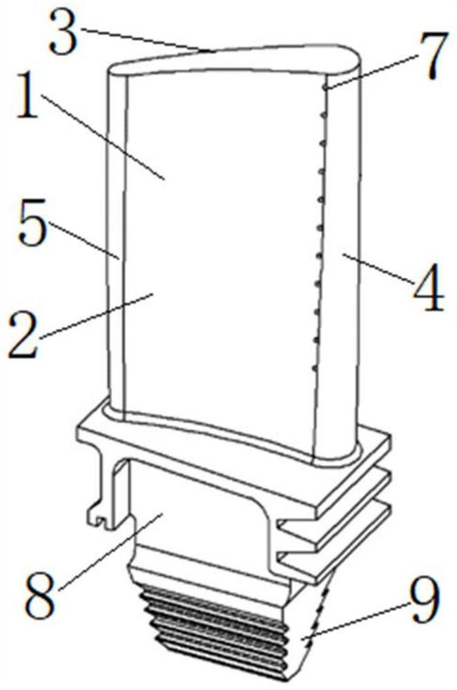
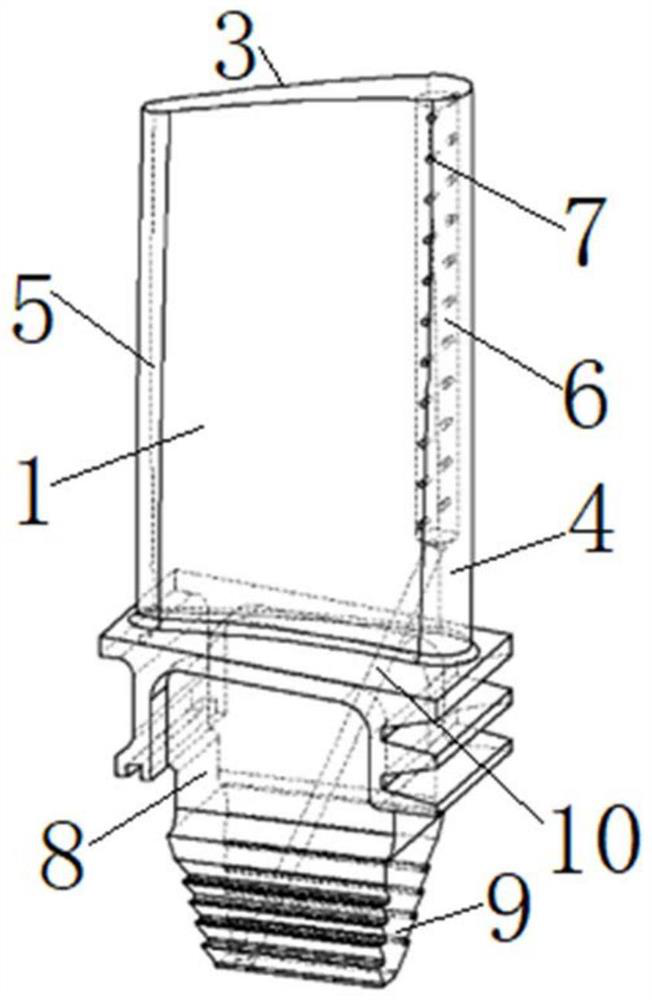
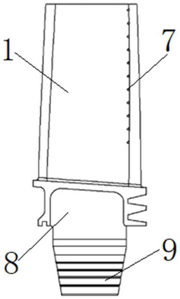
[0039] as attached Figure 1-5 As shown, Embodiment 1 provides a turbine blade, including a blade body 1 and a blade root 8; the blade body 1 has a preset twist angle, and the whole of the blade body 1 is a center-symmetric structure; The preset torsion angle is 20°; the blade body 1 is fixedly arranged at one end of the blade root 8, and the other end of the blade root 8 is used to be connected with the wheel disc; the blade body 1 includes the inner part of the blade Profile 2, blade back profile 3, blade inlet edge 4 and blade outlet side 5; the blade inner profile 2, blade back profile 3, blade inlet side 4 and blade outlet side 5 are enclosed to form the blade body 1.

[0040] The inside of the airfoil 1 is provided with a first cooling air passage 6, the first cooling air passage 6 extends along the length direction of the airfoil 1, and is arranged close to the air inlet edge 4 of the airfoil; A first air film hole 7 and a second air film hole are symmetrically arrang...

Embodiment 2

[0051] The structure and principle of a turbine blade provided in Embodiment 2 are basically the same as those of the turbine blade described in Embodiment 1, except that the special-shaped air film holes are the double-inclined round and right-angle air film holes.

[0052] as attached Figure 8 As shown, the double oblique circular right-angle air film hole includes a second oblique circular hole segment and a third oblique circular hole segment, and the inlet end of the second oblique circular hole segment is communicated with the first cooling air passage 6, The outlet end of the second oblique circular hole segment is connected with the inlet end of the third oblique circular hole segment, and the outlet end of the third oblique circular hole segment is connected to the surface of the blade inner profile 2 or the blade. The surfaces of the back mold surface 3 communicate with each other.

[0053] In this embodiment 2, the included angle between the hole axis of the secon...

Embodiment 3

[0057] The structure and principle of a turbine blade provided in Embodiment 3 are basically the same as those of the turbine blade described in Embodiment 1, except that the special-shaped air film holes are double-inclined circular V-shaped air film holes.

[0058] as attached Figure 9 As shown, the double oblique circular V-shaped air film hole includes a fourth oblique circular hole segment and a fifth oblique circular hole segment; the inlet end of the fourth oblique circular hole segment is communicated with the first cooling air passage 6 , the outlet end of the fourth oblique circular hole segment is connected to the inlet end of the fifth oblique circular hole segment, and the outlet end of the fifth oblique circular hole segment is connected to the surface of the blade inner profile 2 or the The surfaces of the blade back profile 3 are connected; wherein, the fourth oblique circular hole segment and the fifth oblique circular hole segment are located on the same tra...


PUM


Abstract

The invention discloses a turbine blade and an aero-engine. The turbine blade comprises a blade body and a blade root. The blade body is fixedly arranged at one end of the blade root, and the other end of the blade root is matched and connected with a wheel disc; a first cooling gas path is arranged in the blade body, extends in the length direction of the blade body and is arranged close to the blade body gas inlet edge of the blade body. A first air film hole and a second air film hole are symmetrically formed in the two sides of the first cooling air path; the first air film hole extends to the surface of the blade inner molded surface of the blade body; the second air film hole extends to the surface of the blade back molded surface of the blade body; a second cooling gas path is arranged in the blade root, one end of the second cooling gas path is communicated with the first cooling gas path, and the other end of the second cooling gas path extends to the surface of the bottom end of the blade root; the first cooling gas path and the second cooling gas path are circulating channels of a cooling medium; under the condition that the structural weight and size of the blade are not increased, vibration generated when the turbine blade works is effectively restrained; and the structure is simple, machining is convenient, and stability is high.

Description

technical field [0001] The invention belongs to the technical field of turbine blade vibration reduction, and in particular relates to a turbine blade and an aero-engine. Background technique [0002] For aero-engine, turbine blade is an important component; turbine blade is generally subjected to the coupling effect of high centrifugal load and uneven excitation force in the working state, which makes the blade vibrate; and the vibration problem of turbine blade is serious It affects the stable operation of the aero-engine system, and will lead to the destruction of the blade structure, resulting in the loss of life and property; therefore, a new vibration reduction technology is required to solve the vibration problem of turbine blades. [0003] At present, in order to reduce the vibration of the blade during operation, most designers focus on adding structural dampers to the blade or impeller. However, the structural damper will increase the technological difficulty of b...

Claims


Application Information

Patent Timeline
Patent Type & Authority Applications(China)
IPC IPC(8): F01D5/16F01D5/18
CPCF01D5/16F01D5/186F05D2260/202Y02E10/72
Inventor 连业达鲁昊王俊东
Owner NORTHWESTERN POLYTECHNICAL UNIV
Why Eureka
Try Eureka