High-rotating-speed long-shaft transmission vertical centrifugal pump unit and mounting method

A high-speed, centrifugal pump technology, applied in the field of centrifugal pumps, can solve the problems of troublesome transportation or cleaning of long-axis centrifugal pumps, inconvenient cleaning or maintenance of connecting pipes, etc., and achieve the effect of convenient transportation or cleaning and reducing the occupied space

Pending Publication Date: 2022-08-09
湖南中泰水电建设工程有限公司
View PDF1 Cites 0 Cited by
  • Summary
  • Abstract
  • Description
  • Claims
  • Application Information

AI Technical Summary

Problems solved by technology

[0004] Regarding the above-mentioned related technologies, the inventor found that: when transporting or cleaning the long-axis centrifugal pump, since the axial flow pump and the centrifugal pump are connected through the connecting pipe, the length of the entire long-axis centrifugal pump is relatively long, and the impeller inside the connecting pipe is damaged or damaged. When there are debris, it is inconvenient to clean or maintain the connecting pipe, which makes it more troublesome to transport or clean the long-axis centrifugal pump

Method used


Image

  • High-rotating-speed long-shaft transmission vertical centrifugal pump unit and mounting method
  • High-rotating-speed long-shaft transmission vertical centrifugal pump unit and mounting method
  • High-rotating-speed long-shaft transmission vertical centrifugal pump unit and mounting method

Examples


Embodiment Construction

[0050] Attached to the following Figure 1-6 This application will be described in further detail.

[0051] The embodiment of the present application discloses a high-speed long-shaft transmission vertical centrifugal pump unit.

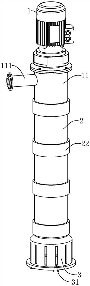
[0052] refer to figure 1 , the vertical centrifugal pump unit includes a motor 1, a conveying cylinder sleeved on the motor 1, the conveying cylinder includes a number of detachable connecting cylinders 2, the connection cylinder 2 away from the motor 1 is threadedly connected with a liquid inlet cover 3, several The connecting cylinders 2 are screwed and fixed to each other. The motor 1 is fixedly connected with a fixing cylinder 11 , the output shaft 12 of the motor 1 extends into the fixing cylinder 11 , and the connecting cylinder 2 close to the motor 1 is fixed to the fixing cylinder 11 through screw connection. The circumferential side wall of the liquid inlet cover 3 is provided with a number of liquid inlets 31, the circumferential side wa...


PUM


Abstract

The invention relates to a high-rotating-speed long-shaft transmission vertical centrifugal pump unit and an installation method, the high-rotating-speed long-shaft transmission vertical centrifugal pump unit comprises a motor and a conveying cylinder arranged on the motor in a sleeving mode, the conveying cylinder comprises a plurality of detachably-connected connecting cylinders, a transmission shaft is rotationally arranged in the connecting cylinders, a plurality of impellers are arranged on the circumferential side wall of the transmission shaft, and the transmission shaft is used for being coaxially connected with an output shaft of the motor; mounting grooves allowing the upper ends of the adjacent transmission shafts to be inserted are formed in the output shaft of the motor and the lower ends of the transmission shafts, a plurality of hinge grooves are formed in the mounting grooves, locking rods are hinged in the hinge grooves, locking grooves are formed in the circumferential side walls of the transmission shafts, driving rods are connected to the locking rods, and the driving rods are used for being connected with the transmission shafts in an abutting mode to drive the locking rods to rotate into the locking grooves; the transmission shaft is further provided with an unlocking piece for driving the locking rod to rotate out of the locking groove. According to the long-shaft centrifugal pump, the connecting cylinder is divided into multiple sections, so that the impeller is conveniently overhauled and cleaned, the occupied space of the whole centrifugal pump is reduced, and the long-shaft centrifugal pump has the advantage that the long-shaft centrifugal pump is convenient to transport or clean.

Description

technical field [0001] The present application relates to the technical field of centrifugal pumps, in particular to a high-speed long-shaft transmission vertical centrifugal pump unit and an installation method. Background technique [0002] At present, vertical centrifugal pumps are widely used. For the use in different environments, long-axis submerged centrifugal pumps are derived from vertical centrifugal pumps. The long-axis submerged centrifugal pump is a kind of medium that inserts the entire pump body into the medium to transport sewage, circulating water and fixed liquid mixed slurry. [0003] Relevant technologies such as a safe, water-saving and low-fault double-tube long-axis submerged pump disclosed in Bulletin No. CN102536846A include a motor, a bottom plate, a liquid outlet pipe, a connecting pipe, an axial flow pump and a centrifugal pump, and a centrifugal pump is provided below the bottom plate. The centrifugal pump is provided with a centrifugal impeller...

Claims


Application Information

Patent Timeline
Patent Type & Authority Applications(China)
IPC IPC(8): F04D29/044F04D29/046F04D29/08F04D29/60
CPCF04D29/044F04D29/046F04D29/086F04D29/605F05D2240/50F05D2240/55F05D2240/60
Inventor 邓策李煜唐雨虹邓荣
Owner 湖南中泰水电建设工程有限公司
Why Eureka
Try Eureka