
Rock core drilling device for geological exploration

A technology for geological exploration and core drilling, which is applied in the field of core drilling devices, can solve the problems of incomplete cooling position of the drill bit, troublesome drilling rig fixing and moving, and shortening the life of the drill bit, etc., and achieves the effects of convenient splicing, rapid splicing and efficiency improvement.

Active Publication Date: 2022-08-09
LANZHOU CITY UNIV
View PDF8 Cites 2 Cited by
  • Summary
  • Abstract
  • Description
  • Claims
  • Application Information

AI Technical Summary

Problems solved by technology

[0003] In the prior art, drilling rigs and drill pipes are used to achieve geological core sampling. However, when using drilling rigs and drill pipes for core drilling, the drilling rig needs to be fixed above the sampling area, and the drilling rig needs to be removed after the drilling is completed. The drill pipe and core samples can be taken out, but the fixing and moving of the drilling rig is troublesome. Moreover, since the core sampling needs to use multiple drill pipes for splicing, each time the drill pipes are spliced, the drill pipes need to be calibrated, and the splicing efficiency is low. ; And the use of drilling fluid in the prior art to cool the drill bit is not comprehensive, and the cooling effect is poor, resulting in a decrease in the life of the drill bit

Method used


Image

  • Rock core drilling device for geological exploration
  • Rock core drilling device for geological exploration
  • Rock core drilling device for geological exploration

Examples


no. 1 example

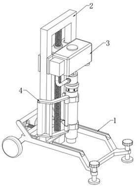
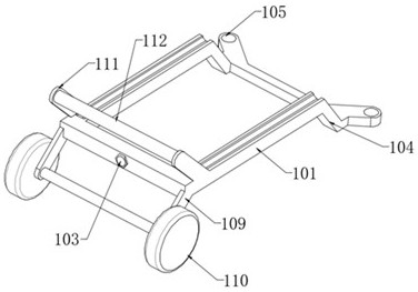
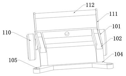
[0042] like Figure 1 to Figure 13 As shown, a core drilling device for geological exploration includes a support assembly 1, a lifting assembly 2, a drilling assembly 3 and an auxiliary assembly 4. The middle of the upper surface of the support assembly 1 is provided with a lifting assembly 2, which lifts the The assembly 2 is slidably connected with the support assembly 1 to adjust the position of the hoisting assembly 2 on the support assembly 1 according to usage requirements. One side of the lifting assembly 2 is provided with a drilling assembly 3, and the drilling assembly 3 can move up and down along the lifting assembly 2, so as to adjust the height of the drilling assembly 3 according to the usage requirements. The outer bottom end of the lifting assembly 2 is provided with an auxiliary assembly 4 .

[0043] Support assembly 1, the support assembly 1 includes a support frame 101, the upper surface of the support frame 101 is provided with two symmetrically distribut...

no. 2 example

[0054] In the actual drilling work of cores, rock layers with different hardness are often drilled. When drilling hard rock formations, the high-speed rotating drill bit will heat up sharply. If the drill bit cannot be rapidly cooled by a large amount of drilling fluid, the life of the drill bit will be affected; while the traditional drilling device, after the drill bit drills the core, When the core enters the drill pipe, the supplied drilling fluid can only reach the drill bit through the small gap between the outer surface of the core and the inner wall of the drill pipe. As a result, the feeding amount of drilling fluid for cooling the drill bit is small, and the rapidly heated drill bit cannot be rapidly cooled in a timely and effective manner, which affects the life of the drill bit. Therefore, the structure of the drill pipe 320 is further improved to address the above problems.

[0055] like Figures 14 to 15 As shown, the inner wall of the drill pipe 320 is axially ...

no. 3 example

[0059] On the basis of the above embodiment, due to the improvement of the drilling fluid supply path, a large-flow liquid flow path can be formed to the drill bit through the liquid guiding groove 329, the guiding hole 330, and the limiting groove 326. When the drill bit 331 gets stuck in the core 332, the high-pressure pulsating water flow can be supplied through the booster pump 316, and the high-pressure pulsating water flow can pass through the liquid guide groove 329, the guide hole 330, and the limit groove 326 to the drill bit 331. The impact force is generated, and under the action of the reaction force of the impact force, a reverse driving force can be generated on the drill bit 331 and the drill pipe 320, which is conducive to the removal of the drill. Compared with the traditional core drilling device (the supplied drilling fluid can only reach the drill bit through the small gap between the outer surface of the core and the inner wall of the drill pipe, and cannot...


PUM


Abstract

The invention discloses a rock core drilling device for geological exploration, and relates to the technical field of geological exploration drilling equipment, the rock core drilling device comprises a supporting assembly, a lifting assembly, a drilling assembly and an auxiliary assembly, the lifting assembly is arranged on the upper surface of the supporting assembly, the drilling assembly is arranged on one side of the lifting assembly, and the auxiliary assembly is arranged on the other side of the lifting assembly. An auxiliary assembly is arranged at the bottom end of the outer side of the lifting assembly. By arranging the supporting assembly, the lifting assembly, the drilling assembly and the auxiliary assembly, the supporting assembly can achieve movement and placement positioning of the device, and the lifting assembly can drive the drilling assembly to move up and down, so that a drill rod can conveniently drill into the ground, and the drilling assembly can drill the drill rod into the ground and complete sampling; and the auxiliary assembly can be used for carrying out auxiliary positioning on the drill rod, so that the drill rod is convenient to splice, the core drilling efficiency is improved, and geological exploration work is convenient to carry out.

Description

technical field [0001] The invention relates to the technical field of geological exploration drilling equipment, in particular to a core drilling device for geological exploration. Background technique [0002] "Geological exploration" refers to the investigation and research of geological exploration and detection through various means and methods, to determine the appropriate bearing layer, to determine the foundation type and to calculate the basic parameters according to the bearing capacity of the bearing layer. It is the discovery of industrially significant deposits in the mineral census, in order to find out the quality and quantity of minerals, as well as the technical conditions for mining and utilization, to provide mineral reserves and geological data required for mine construction and design, and to analyze the rocks and strata in a certain area. , structure, minerals, hydrology, landforms and other geological conditions to conduct investigation and research wo...

Claims


Application Information

Patent Timeline
Patent Type & Authority Applications(China)
IPC IPC(8): G01N1/08
CPCG01N1/08Y02E10/10
Inventor 欧阳征健张涛冯娟萍杨斌郭庆马东旭刘璎
Owner LANZHOU CITY UNIV
Learn More