Ceramic tile adhesive bonding force testing device

A testing device and bonding force technology, applied in the direction of measuring devices, mechanical devices, instruments, etc., can solve problems such as tile damage and difficulty in ensuring measurement accuracy, and achieve the effect of ensuring testing accuracy, avoiding waste of raw materials, and reducing testing time.

Pending Publication Date: 2022-08-09
江西亿彩涂料股份有限公司
View PDF1 Cites 2 Cited by
  • Summary
  • Abstract
  • Description
  • Claims
  • Application Information

AI Technical Summary

Problems solved by technology

[0005] In order to overcome the shortcomings of the existing tile adhesive adhesion testing device that would cause damage to tiles and make it difficult to ensure measurement accuracy, a tile adhesive adhesion testing device that would not damage tiles and ensure measurement accuracy was provided

Method used


Image

  • Ceramic tile adhesive bonding force testing device
  • Ceramic tile adhesive bonding force testing device
  • Ceramic tile adhesive bonding force testing device

Examples


Embodiment 1

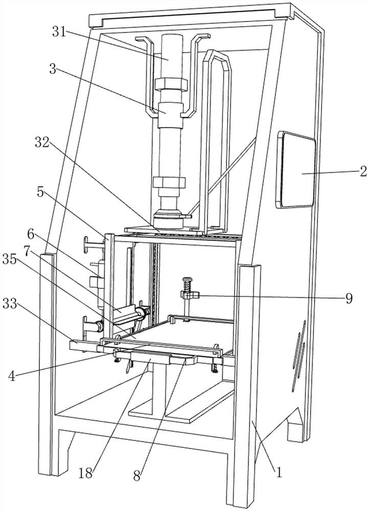
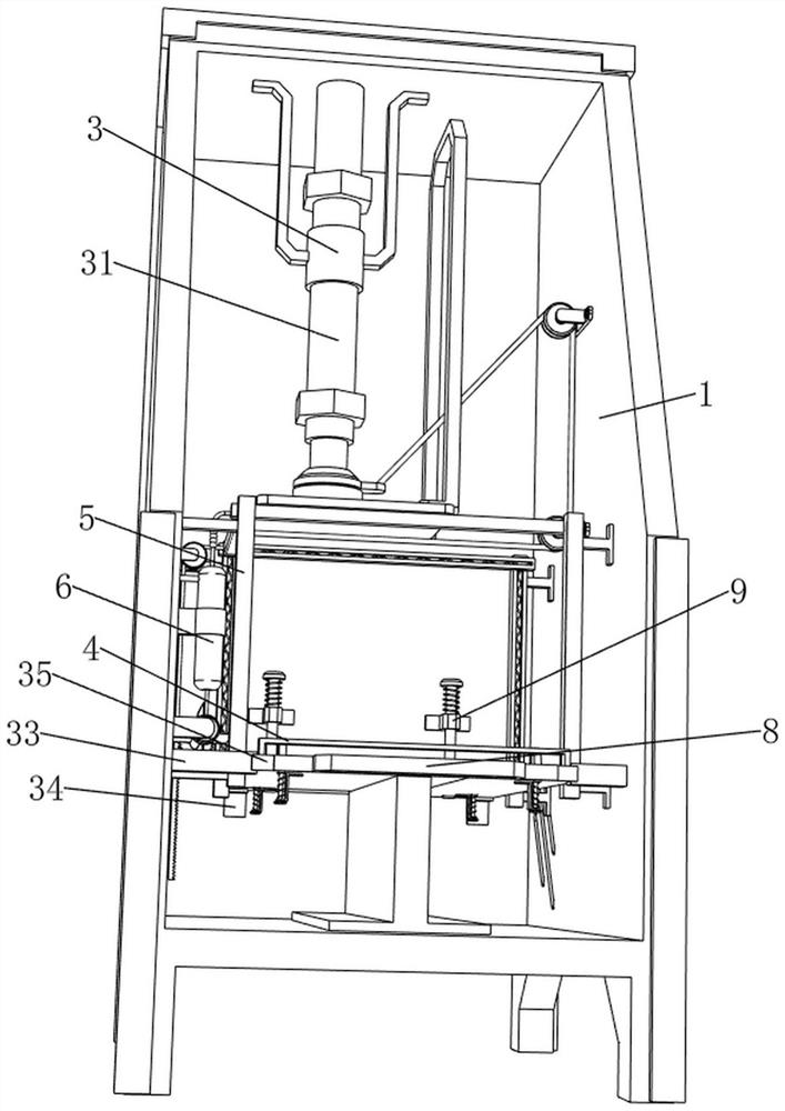
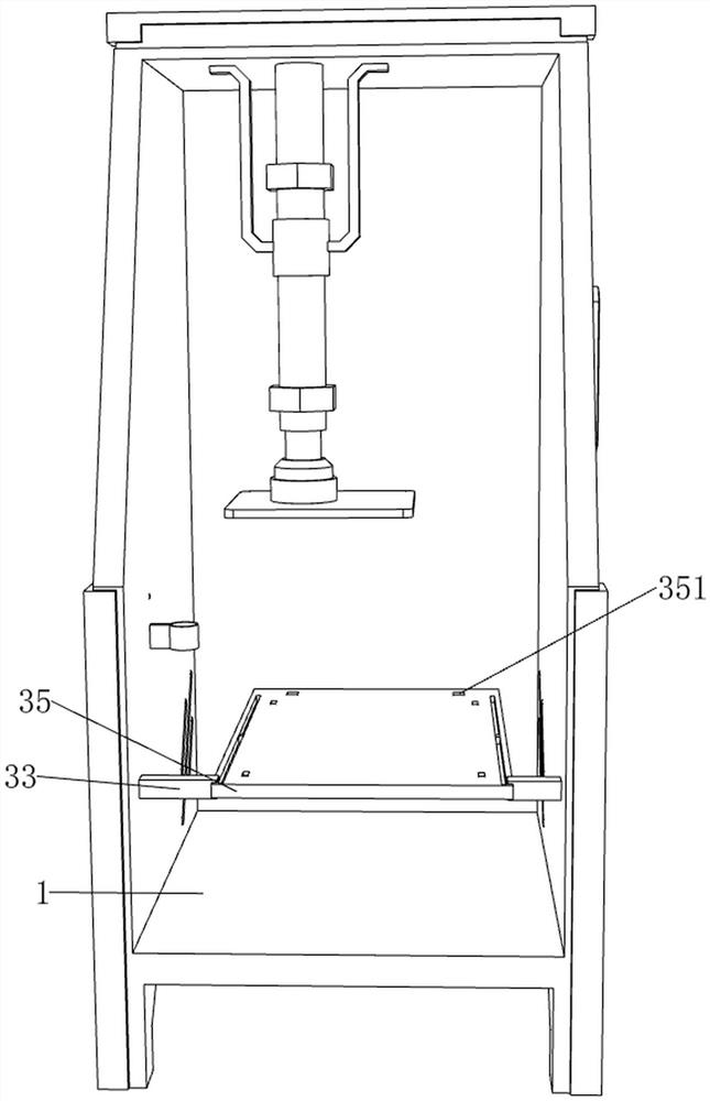
[0037] A tile adhesive bonding force testing device, refer to Figure 1-Figure 3As shown, it includes an outer frame 1, a display screen 2, a first fixing ring 3, a cylinder 31, a drawing plate 32, a support rod 33, a support plate 34, a storage table 35, a limiting mechanism 4 and a coating mechanism 5, the outer frame 1 A display screen 2 is fixed on the upper side of the right part, and the display screen 2 can display the tensile force value. A first fixing ring 3 is fixed on the left front side of the inner top of the outer frame 1; The bottom of the telescopic rod is fixed with a pulling plate 32, the front side of the lower part of the outer frame 1 is fixed with support rods 33 symmetrically left and right, the lower part of the inner rear wall of the outer frame 1 is fixed with a support plate 34 symmetrically left and right, and the support rods 33 are slidably connected. There is an object table 35, and the object table 35 is in contact with the support plate 34. Th...

Embodiment 2

[0042] On the basis of Example 1, refer to figure 1 , Figure 9 and Figure 10 As shown, it also includes an air-drying mechanism 6, which can speed up the drying of glue, and the air-drying mechanism 6 includes a second pulling rope 61, a second guide wheel 62, a toothed rod 63, a gear 64, a rotating shaft 65, a torsion spring 66, a first Four fixed rods 67 , fan blades 671 , third slide rails 68 and fifth springs 69 , a second guide wheel 62 is fixedly connected to the rear side of the lower part of the inner left wall of the outer frame 1 , and a second guide wheel 62 is fixedly connected to the rear side of the lower part of the inner left wall of the outer frame 1 The third slide rail 68 , the third slide rail 68 is located on the lower side of the second guide wheel 62 , the inner and lower side of the third slide rail 68 is slidably provided with a toothed rod 63 , and the toothed rod 63 and the third slide rail 68 are connected with a first Five springs 69, a second ...


PUM


Abstract

The invention relates to a bonding force testing device, in particular to a tile adhesive bonding force testing device. The invention provides the tile adhesive bonding force testing device which does not damage tiles and ensures the measurement precision. According to the technical scheme, the tile adhesive bonding force testing device comprises an outer frame, a display screen, a first fixing ring, an air cylinder, a drawing plate and the like, the display screen capable of displaying the tension value is installed on the upper side of the right portion of the outer frame, the first fixing ring is installed on the left front side of the top in the outer frame, and the air cylinder is installed in the middle of the first fixing ring; a drawing plate is mounted at the bottom of the cylinder telescopic rod. The adhesive force of the glue can be well reflected by the tension value displayed by the display screen, so that the testing precision is guaranteed, the ceramic tile is not damaged during testing, and the waste of raw materials can be avoided.

Description

technical field [0001] The invention relates to an adhesive force testing device, in particular to a tile adhesive adhesive force testing device. Background technique [0002] Tile adhesive has good flexibility and can prevent the production of empty drums. It is a good bonding material. After the tile adhesive is produced, in order to avoid the tiles falling off due to quality problems in the later use process, it is necessary to first adjust the tile adhesive. Adhesion test. [0003] Patent Publication No. CN209296547U discloses a ceramic tile adhesive bonding force testing device, including a base and a tension plate, the tension plate is provided with a pull ring for hanging weights and a number of threaded through holes; both sides of the base are There is a water spray device, the water spray device is two water guns installed on the rotating shaft and rotates around the rotating shaft; the other two sides of the base are provided with hot air devices, and the hot air...

Claims


Application Information

Patent Timeline
Patent Type & Authority Applications(China)
IPC IPC(8): G01N19/04
CPCG01N19/04
Inventor 周丽萍黄诚黄清卫陈良平
Owner 江西亿彩涂料股份有限公司
Why Eureka
Try Eureka