Large dynamic measurement range current sensing method and circuit

A technology of measurement range and sensing method, applied in the direction of measuring current/voltage, measuring electrical variables, measuring devices, etc., can solve the problems of chip area loss, measurement accuracy error, etc., achieve random noise error suppression, improve test accuracy, and improve Effect of dynamic measurement range

Pending Publication Date: 2022-08-09
TONGJI UNIV
View PDF0 Cites 0 Cited by
  • Summary
  • Abstract
  • Description
  • Claims
  • Application Information

AI Technical Summary

Problems solved by technology

[0004] In order to obtain a larger measurement range, the traditional current-voltage conversion system will set a control signal to change the integral capacitor through the switch gati

Method used


Image

  • Large dynamic measurement range current sensing method and circuit
  • Large dynamic measurement range current sensing method and circuit
  • Large dynamic measurement range current sensing method and circuit

Examples


Example Embodiment

[0038] The preferred embodiments of the present invention will be described in detail below with reference to the accompanying drawings, so as to more clearly understand the objects, features and advantages of the present invention. It should be understood that the embodiments shown in the accompanying drawings are not intended to limit the scope of the present invention, but are only intended to illustrate the essential spirit of the technical solutions of the present invention.

[0039]In the following description, for the purpose of illustrating various disclosed embodiments, certain specific details are set forth in order to provide a thorough understanding of the various disclosed embodiments. One skilled in the relevant art will recognize, however, that embodiments may be practiced without one or more of these specific details. In other instances, well-known devices, structures and techniques associated with this application may not be shown or described in detail to avo...


PUM


Abstract

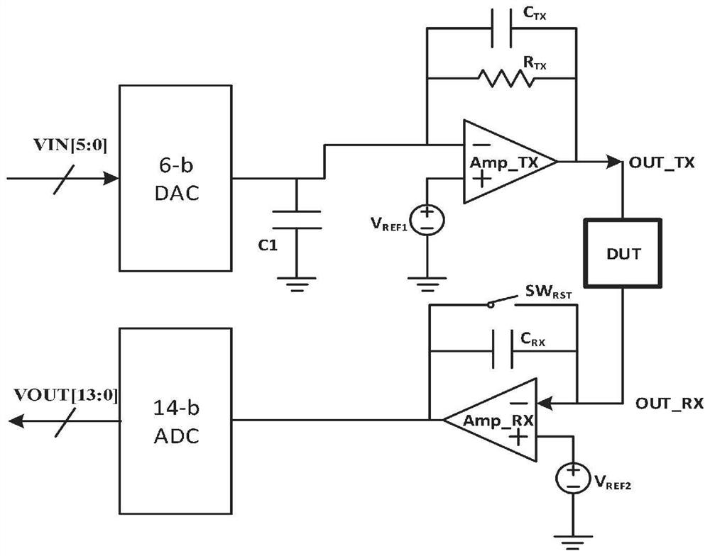
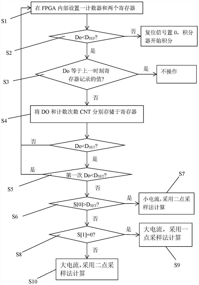
The invention discloses a large dynamic measurement range current sensing method and circuit, and the circuit comprises an FPGA, a DAC, a signal transmitting module, a signal receiving module, and an ADC. A counter for measuring integral time is arranged in the FPGA, and ADC sampling bits are expanded by using the bits of the counter, so that the dynamic measurement range of the current is expanded, and the measurement of the whole sensing circuit is automated and simplified. The integrator of the signal receiving module only adopts one integrating capacitor, gear shifting is not needed, a traditional switch used for replacing capacitor gears is omitted, and leakage current and chip area caused by the switch in a circuit are effectively reduced.

Description

technical field [0001] The invention belongs to the technical field of integrated circuits, and in particular relates to a large dynamic measurement range current sensing method and circuit. Background technique [0002] With the development of science and technology, more and more technologies need to have higher precision and high-range sensing requirements for current signals. In different applicable scenarios, the applied current sensing circuits also have different requirements. In the fields of medical precision instruments and materials research, the difference in the picoamp level of current means two completely different results. At the same time, for practical applications, currents of pico-ampere to nano-ampere or even micro-ampere level may appear in a system. [0003] Since the magnitude and range of the current to be detected by the current sensing circuit are not uniform in different fields, different current sensing methods can be used in different fields. ...

Claims


Application Information

Patent Timeline
IPC IPC(8): G01R19/255
CPCG01R19/255G01R19/0023
Inventor 程琪德邱雷
Owner TONGJI UNIV
Why Eureka
Try Eureka