Target real-time tracking control method and system

A technology of real-time tracking and control methods, applied in image analysis, instrumentation, computing and other directions, can solve the problems of small area array single photon pixels, inability to track and image targets, difficult to search and find targets, etc., to achieve a large transient field of view, Conducive to accurate tracking and high computing efficiency

Pending Publication Date: 2022-08-09
INST OF APPLIED ELECTRONICS CHINA ACAD OF ENG PHYSICS
View PDF5 Cites 2 Cited by
  • Summary
  • Abstract
  • Description
  • Claims
  • Application Information

AI Technical Summary

Problems solved by technology

[0003] However, due to the small number of single-photon pixels in the area array, generally only 32×32 or 64×64 arrays, the detection field of view of the target is generally small, only a few tenths to a few milliradians, and it is difficult to search and find the target
I

Method used


Image

  • Target real-time tracking control method and system
  • Target real-time tracking control method and system
  • Target real-time tracking control method and system

Examples


Embodiment 1

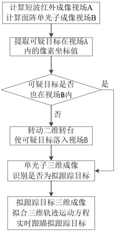
[0062] The target tracking control method of the present invention comprises the following steps:

[0063] First, initialize the system. After the initialization is qualified, perform the following steps:

[0064] (1) Calculate the visible range of passive short-wave infrared imaging and active area array single-photon imaging, that is, based on the imaging mirror axis of the two-dimensional turntable, calculate the field of view range A of passive short-wave infrared imaging and active area array single-photon imaging. Field of view B;

[0065] (2) Use passive short-wave infrared imaging to detect suspicious targets in the area to be tested. When the suspicious target enters the field of view A of the passive short-wave infrared, the pixel coordinate value of the detected suspicious target is extracted by the integral map method;

[0066] (3) Determine whether the pixel coordinate value of the suspicious target is within the field of view B of the active area array single ph...

Embodiment 2

[0099] The target tracking control method of the present invention comprises the following steps:

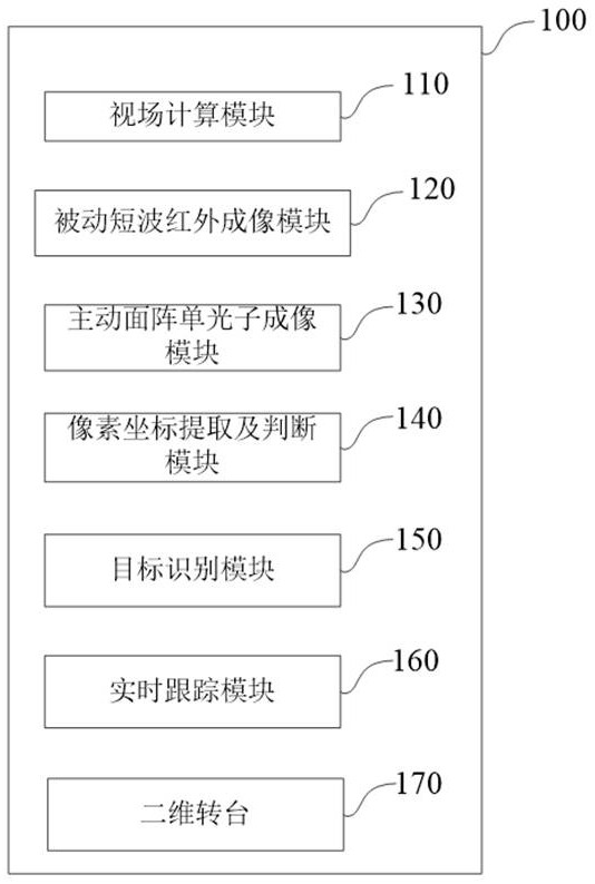
[0100] A target real-time tracking control system 100 includes: a field of view calculation module 110, a passive short-wave infrared imaging module 120, an active area array single-photon imaging module 130, a pixel coordinate extraction and judgment module 140, a target recognition module 150, and a real-time tracking module 160 and a two-dimensional turntable 170;

[0101] The field of view calculation module 110 is used to calculate the visible range of the passive short-wave infrared imaging module and the active area array single-photon imaging module. Specifically: using the imaging mirror axis of the two-dimensional turntable 170 as a benchmark, calculate the field of view range A of the passive short-wave infrared imaging module 120 and the field of view range B of the active area array single-photon imaging module 130;

[0102] The passive short-wave infrared imaging ...


PUM


Abstract

The invention discloses a target real-time tracking control method and system. The method comprises the steps of calculating a short-wave infrared field of view A and an area array single-photon imaging field of view B, extracting pixel coordinates of a suspicious target in the field of view A, judging whether the suspicious target is in the field of view B or not, if not, rotating a rotary table to enable the suspicious target to fall in the field of view B, and identifying whether the suspicious target is a target to be tracked or not through single-photon three-dimensional imaging. And performing three-dimensional imaging on the to-be-tracked target according to the time interval, and fitting a three-dimensional trajectory equation to follow and aim the to-be-tracked target in real time. The system comprises a view field calculation module, a passive short-wave infrared imaging module, an active area array single-photon imaging module, a pixel coordinate extraction and judgment module, a target identification module, a real-time tracking module and a two-dimensional turntable. According to the method and the device, rough positioning and reliable extraction of the suspicious target can be rapidly realized, and the motion track can be predicted in real time by using historical data of the target, so that a reference is provided for capturing the target again after the target is lost.

Description

technical field [0001] The invention belongs to the technical field of target control, in particular to a target real-time tracking control method, and also to a target real-time tracking control system. Background technique [0002] When a moving target moves rapidly, its background may be clouds and nature, and the environment in which it moves may be a low-light environment or an environment without natural light illumination, and sometimes there may be smoke and fog between the target and the detector. In other cases, in order to track and detect such moving targets, the area array single photon is often used to have certain physical properties of penetrating smoke, and active area array single photon imaging is used to actively detect the target. [0003] However, due to the small number of single-photon pixels in the area array, generally only 32 × 32 or 64 × 64 arrays, the detection field of view of the target is generally small, only a few tenths to a few milliradian...

Claims


Application Information

Patent Timeline
IPC IPC(8): G06T7/246G06T7/215G01V8/10
CPCG06T7/246G06T7/215G01V8/10G06T2207/10028G06T2207/30241
Inventor 潘文武李旭孙会田俊林姚宇翔冯弟超王智涌郑晓东张家如
Owner INST OF APPLIED ELECTRONICS CHINA ACAD OF ENG PHYSICS
Why Eureka
Try Eureka