GIS-based territorial space planning system and planning display equipment thereof

A technology for space planning and display equipment, applied in mechanical equipment, ICT adaptation, identification devices, etc., can solve the problems of inability to plan the image and the basic image coverage comparison, single display, poor display effect, etc. The effect of good contrast effect and simple locking method

Pending Publication Date: 2022-08-09
山东纵阡规划设计有限公司
0 Cites 0 Cited by

AI-Extracted Technical Summary

Problems solved by technology

[0004] Aiming at the deficiencies of the prior art, the present invention provides a GIS-based land space planning system and its planning display equipment, which solves the problem that the currently used ...

Method used

Please refer to Fig. 1-7, on the basis of embodiment one and embodiment two, the present invention provides a kind of technical scheme: sliding device 5 comprises sliding seat 51, and sliding seat 51 one end is provided with supporting roller 52, and sliding seat 51 The limit roller 53 is arranged on the side, and the end side close to the support roller 52 on the sliding seat 51 is fixedly connected with a rotating sleeve 54, and the inner wall of the rotating sleeve 54 is rotatably connected with a ball 55. The shape of the sliding seat 51 is L-shaped, and the bottom of the sliding seat 51 is connected with a transparent The display screen 4 is fixedly connected, the end of the sliding seat 51 close to the supporting roller 52 extends to the inside of the inner chute 6, and the side of the limit roller 53 away from the side of the sliding seat 51 extends to the inside of the outer chute 7, and a sliding device 5 is provided. The sliding seat 51 inside the device 5 is arranged in an L shape, which can be fixed to the transparent display screen 4...

Abstract

The invention discloses a GIS-based territorial space planning system and planning display equipment thereof, and the system comprises a central processing module which is used for the conversion processing, integration and transmission of data, and is internally provided with an A/D converter; the output end of the planning data module is electrically connected with the input end of the central processing module, and predicted planning data is stored in the planning data module; the output end of the basic data module is electrically connected with the input end of the central processing module, and existing planning data are stored in the basic data module. According to the GIS-based territorial space planning system and the planning display equipment thereof, the comparison effect is relatively good, the basic planning image and the predicted planning image can be sorted independently and can be split at any time, data sorting and use are relatively convenient, and the display screen is relatively convenient to fix and move.

Application Domain

Technology Topic

Image

  • GIS-based territorial space planning system and planning display equipment thereof
  • GIS-based territorial space planning system and planning display equipment thereof
  • GIS-based territorial space planning system and planning display equipment thereof

Examples

  • Experimental program(3)

Example Embodiment

[0050] Example 1:
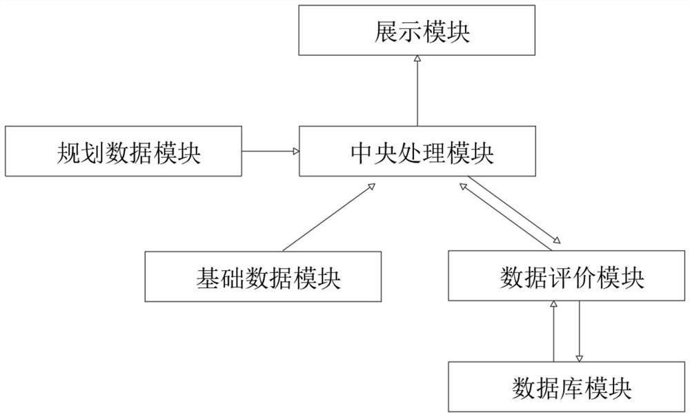
[0051] see figure 1 , the present invention provides a technical solution: a GIS-based land space planning system, comprising:
[0052] A central processing module, which is used for data conversion, integration and transmission, and an A/D converter is arranged inside the central processing module;
[0053] a planning data module, the output end of the planning data module is electrically connected with the input end of the central processing module, and the planning data module internally stores the expected planning data;
[0054] a basic data module, the output end of the basic data module is electrically connected with the input end of the central processing module, and the existing planning data is stored in the basic data module;
[0055] a data evaluation module, the output end and the input end of the data evaluation module are respectively electrically connected with the input end and the output end of the central processing module;
[0056] a database module, the output end and the input end of the database module are respectively electrically connected with the output end and the input end of the data evaluation module;
[0057] The display module is provided with a display device inside the display module, and the input end of the display device inside the display module is electrically connected with the output end of the central processing module.
[0058] The planning data module and the basic data module send the predicted planning data and the basic planning data to the central processing module, and after the central processing module converts and processes the predicted planning data, adds the predicted planning data to the basic planning data, and then transmits the integrated data to the display. Inside the module and the data evaluation module, the integrated data is displayed in the form of images through the display module, and at the same time, the data exchange between the data evaluation module and the database module is used for comparison and evaluation, and then the results are returned to the central processing module. After being processed by the central processing module, the data is transmitted to the inside of the display module, and the evaluation results are displayed again through the display device inside the display module.

Example Embodiment

[0059] Embodiment 2:
[0060] see Figure 1-4 , on the basis of the first embodiment, the present invention provides a technical solution: a planning display device for a GIS-based national land space planning system, including a display module, and a display device is arranged inside the display module;
[0061] The display device includes:
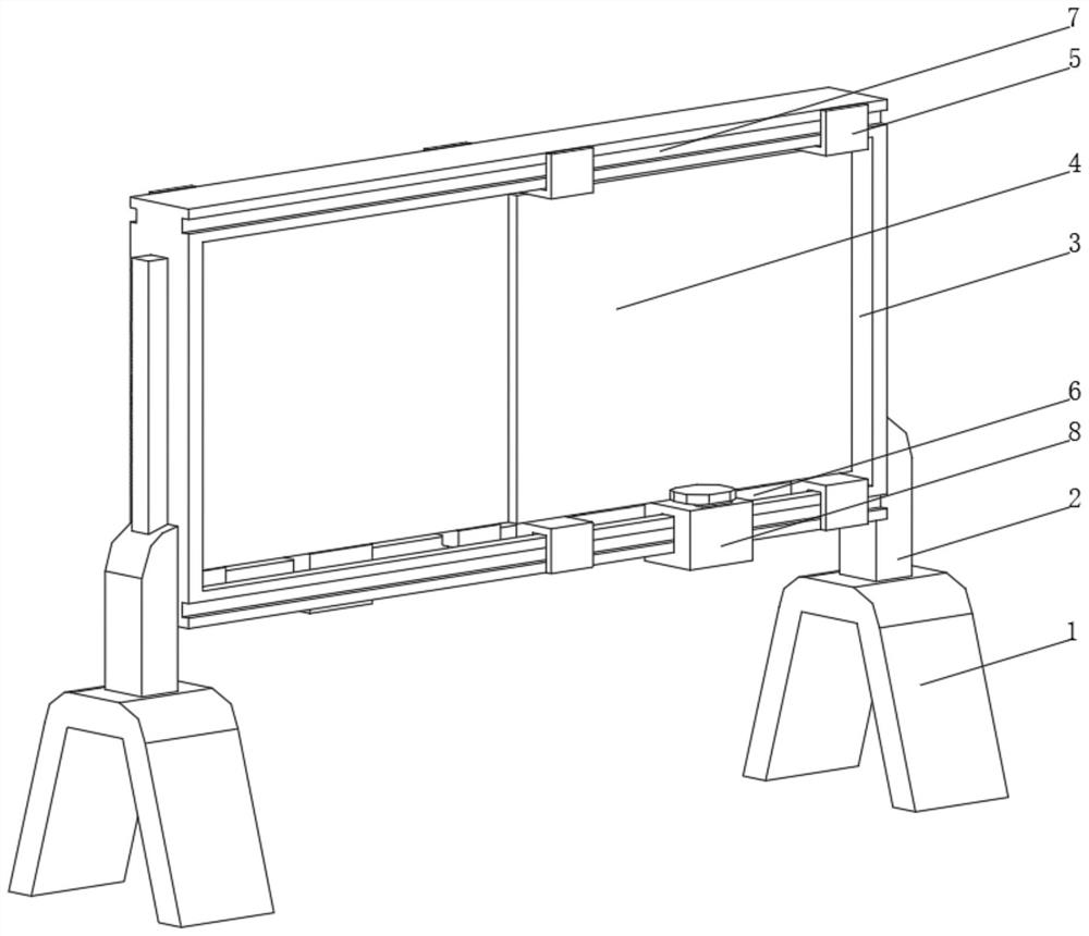
[0062] A fixed bracket 1, the top of the fixed bracket 1 is fixedly connected with a lifting device 2, and a side of the lifting device 2 is fixedly connected with a fixed frame 3;
[0063] A transparent display screen 4, the four corners of the transparent display screen 4 are fixedly connected with a sliding device 5, the side surface and the inner wall of the fixed frame 3 are respectively provided with an inner chute 6 and an outer chute 7 that are adapted to the sliding device 5, and the transparent display screen 4 There are two groups and they are staggered and distributed inside the inner chute 6;
[0064] a fixing device 8, the fixing device 8 is fixed at the bottom of the transparent display screen 4;
[0065] The characteristics of the planning display equipment of the GIS-based national land space planning system are: the fixing device 8 includes:
[0066] A fixed socket 81, a first U-shaped cavity 82 and a second U-shaped cavity 83 are respectively opened in the fixed socket 81, and the first U-shaped cavity 82 and the second U-shaped cavity 83 are communicated through an air passage;
[0067] Pressing piston 84, the pressing piston 84 is arranged inside the first U-shaped cavity 82 at one end away from the second U-shaped cavity 83, and one end of the pressing piston 84 extends to the outside of the first U-shaped cavity 82 and is fixedly connected with a pressing plate 85;
[0068] A compression piston 86, the compression piston 86 is arranged at the end of the inner wall of the second U-shaped cavity 83 away from the first U-shaped cavity 82, and a compression spring 87 is fixedly connected to the top of the compression piston 86;
[0069] The top rod 88, the top of the top rod 88 is fixedly connected with the bottom of the pressing piston 86, the end of the top rod 88 away from the pressing piston 86 penetrates the second U-shaped cavity 83 and extends to the outside of the fixed clip 81, and the top rod 88 is located in the fixed clip. One end outside the seat 81 is fixedly connected with a friction plate 89;
[0070] A feedback device 80 is provided at the bottom of the fixed holder 81 .
[0071] Two sets of transparent display screens 4 are provided, and the two sets of transparent display screens 4 are staggered inside the inner chute 6. When in use, the basic planning image can be transmitted to one set of transparent display screens 4, and the projected planning image can be transmitted to another. On the set of transparent display screens 4, the images of the two sets of transparent display screens 7 can be used for comparative analysis. Since the display screens are transparent, the two sets of transparent display screens 4 can be moved to overlap when necessary, so as to compare the basic planning images with the projected planning images. The images are overlapped together, so that the projected planning image is supplemented to the basic planning image, and the comparison effect is better. The basic planning image and the projected planning image can be sorted separately, and can be split at any time. , when the transparent display screen 4 is fixed, the pressing piston 86 can be pushed down by the pressing spring 87 inside the fixing device 8 to drive the ejector rod 88 and the friction plate 89 on the ejector rod 88 to press the inner wall of the inner chute 6 The bottom of the transparent display screen 4 connected with the fixing device 8 is fixed. When the transparent display screen 4 needs to be moved, the pressing plate 85 can be directly pressed, and the pressing plate 85 drives the pressing piston 84 to compress the air inside the first U-shaped cavity 82 , the air pressure inside the first U-shaped cavity 82 pushes the pressing piston 86 inside the second U-shaped cavity 83 to move upward through the air passage, thereby driving the ejector rod 88 and the friction plate 89 to separate from the inner wall of the inner chute 6, and the transparent display screen 4 is It can be moved without using a bolt and nut structure. The locking method is simple, and the device can be unlocked only by pressing. The pressing operation and the moving operation can be performed at the same time, which is more convenient to use.

Example Embodiment

[0072] Embodiment three:
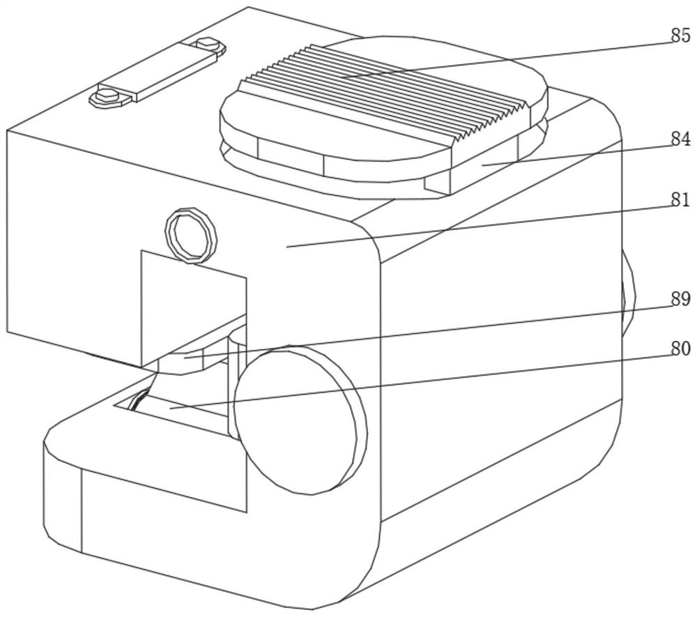
[0073] see Figure 1-6 , on the basis of Embodiment 1 and Embodiment 2, the present invention provides a technical solution: the feedback device 80 includes a rotating groove 801, the inner wall of the rotating groove 801 is rotatably connected with a rotating column 802 through a bearing, and the outer side of the rotating column 802 is sleeved and fixedly connected There is a beating plate 803, a clockwork spring 804 is fixedly connected on both sides of the beating plate 803, a rotating slot 801 is opened at the bottom of the inner wall of the fixed card seat 81, a feedback chute is opened at the bottom of the fixed frame 3, and the inner wall of the feedback chute inside the fixed frame 3 A triangular protrusion is fixedly connected, one end of the beating plate 803 away from the rotating column 802 extends to the inside of the feedback chute and is slidably connected with the triangular protrusion, the side surface of the beating plate 803 is fixedly connected with the central end of the clockwork spring 804, The end is fixedly connected with the inner wall of the rotating slot 801. When the fixing device 8 moves with the transparent display screen 4, the punching plate 803 inside the rotating slot 801 is mobilized to move, and the punching plate 803 moves while pushing the punching plate through the triangular protrusion at the bottom of the fixed frame 3. 803 rotates, when the beating plate 803 is disengaged from the top of the triangular protrusion, the clockwork spring 804 drives the beating plate 803 to reset, and at the same time hits the next group of triangular protrusions, so as to use the knocking sound and the rotational resistance of the beating plate 803 for use. The personnel provide movement feedback, which is convenient for users to judge the movement distance.
[0074] Embodiment three:
[0075] see Figure 1-7, on the basis of Embodiment 1 and Embodiment 2, the present invention provides a technical solution: the sliding device 5 includes a sliding seat 51, one end of the sliding seat 51 is provided with a support roller 52, the side of the sliding seat 51 is provided with a limit roller 53, and the sliding seat A rotating sleeve 54 is fixedly connected to the side of one end of the 51 close to the support roller 52, and the inner wall of the rotating sleeve 54 is rotatably connected with a ball 55. The shape of the sliding seat 51 is L-shaped, and the bottom of the sliding seat 51 is fixedly connected with the transparent display screen 4. One end close to the support roller 52 extends to the inside of the inner chute 6, and the side of the limit roller 53 away from the sliding seat 51 extends to the inside of the outer chute 7, and a sliding device 5 is provided. Since the sliding seat 51 inside the interaction device 5 is set as L-shaped, which can be fixed to the transparent display screen 4 through one end of the L-shaped sliding seat 51, and the other end extends to one side of the transparent display screen 4, so that the sliding seats 51 on the two sets of transparent display screens 4 are separated from the two sets of transparent display screens On the opposite side of the two sets of transparent display screens 4, the opposite sides of the two groups of transparent display screens 4 can be close together, so that when the transparent display screens 4 are overlapped and displayed, the displayed images can be closer to avoid an obvious sense of layered isolation. And a limit roller 53 is provided, and the limit roller 53 and the ball 55 can cooperate to clamp one side edge of the fixed frame 3 in it, and the sliding device 5 can be limited by the cooperation of the fixed frame 3 with the limit roller 53 and the ball 55. Therefore, the position of the transparent display screen 4 connected with the sliding device 5 is prevented from deviating, and the stability is better. At the same time, the ball 55 can reduce the friction between the sliding seat 51 and the inner wall of the inner chute 6, and the moving operation is relatively easy, and Avoid friction gaps.

PUM

no PUM

Description & Claims & Application Information

We can also present the details of the Description, Claims and Application information to help users get a comprehensive understanding of the technical details of the patent, such as background art, summary of invention, brief description of drawings, description of embodiments, and other original content. On the other hand, users can also determine the specific scope of protection of the technology through the list of claims; as well as understand the changes in the life cycle of the technology with the presentation of the patent timeline. Login to view more.

Similar technology patents

Liquid crystal compound and liquid crystal composition containing same, and liquid crystal display device

PendingCN113528152AWide Nematic Temperature RangeGood contrastLiquid crystal compositionsOrganic chemistryDielectric anisotropyRotational viscosity
Owner:JIANGSU HECHENG ADVANCED MATERIALS

Contrast Dyes for Inkjet Lithographic Printing Plates

InactiveUS20090036638A1Good contrastAzo dye preparationMonoazo dyesCarbon atomPhotochemistry
Owner:AGFA NV

Classification and recommendation of technical efficacy words

Why Eureka
Try Eureka