
Laser metal layer removing device of metallized film capacitor winding machine

A metallized film and metal removal technology, applied in the direction of wire wound capacitor machine, metal surface removal regulations, etc., can solve the problems of poor applicability, laser generator metallized film adjustment, etc., to achieve good removal effect and improve the effect of applicability

Pending Publication Date: 2022-08-09
SICHUAN ZHONGXING ELECTRONICS
View PDF1 Cites 0 Cited by
  • Summary
  • Abstract
  • Description
  • Claims
  • Application Information

AI Technical Summary

Problems solved by technology

However, in this patented technical solution, the position of the laser generator cannot be adjusted according to the thickness and width of the metallized film, and only one specification of the metallized film can be removed, which has poor applicability

Method used


Image

  • Laser metal layer removing device of metallized film capacitor winding machine
  • Laser metal layer removing device of metallized film capacitor winding machine
  • Laser metal layer removing device of metallized film capacitor winding machine

Examples


Embodiment 1

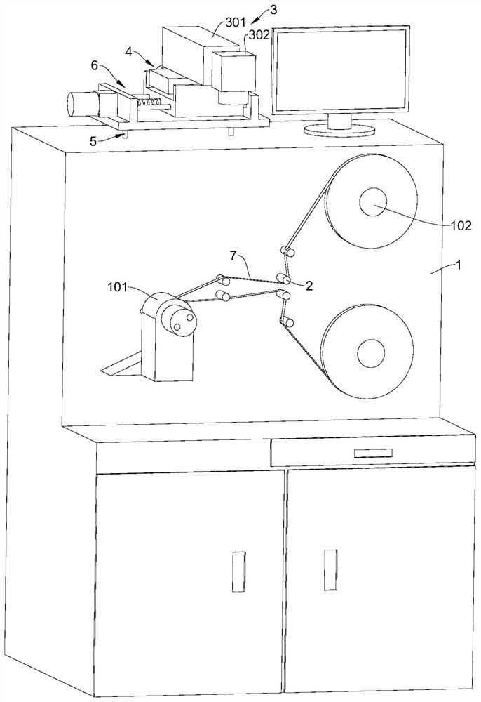
[0040] A metal film capacitor scroll machine laser clearing the metal layer device, including a rolling machine with 101 roll -up mechanism 101 and at least one roll -up mechanism 102. The institutional 101 rolls into the core (also known as Suzi). The closing mechanism 101 can be the same as the existing technology, that is, the rotation of the roller is achieved. Active rollers can drive rotation by connecting to the driver motor. The roller used for rolls does not require power. Of course, in other embodiments, the rollers used and the rollers used for rolls can also be connected to the driver motor, so that the speed of the two can be the same, and it can also achieve the collection and rolls.

[0041] There are two examples of the rolls in this embodiment, which can be wrapped in two layers of metallic film 7. Two thin membranes are superimposed together during the wound, forming a double -layer structure core. In practical applications, only one of them can be used.

[0042]...

Embodiment 2

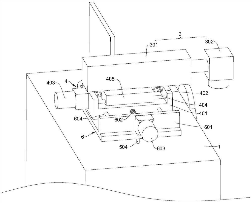
[0052] The difference between this embodiment and Example I is that the structure and embodiments of the X to regulating mechanism 6, and Z to the adjustment mechanism 5 are different.

[0053] In this embodiment, Y to the regulatory agency 4 includes the first driver element, and the first driver element is an electric push rod, a hydraulic push rod or a cylinder. The component drives the laser removal device 3 displacement, thereby adjusting the position of the laser removal device 3 in the direction of the width direction of the metallic film 7.

[0054] X to the regulating mechanism 6 includes the third -wheel drive component, the third -wheel drive element is an electric push rod, a hydraulic push rod or a cylinder. The overall displacement of the regulatory mechanism 4 and the laser removal device 3, thereby adjusting the position between the laser removal device 3 at the closing mechanism 101 and the release mechanism 102.

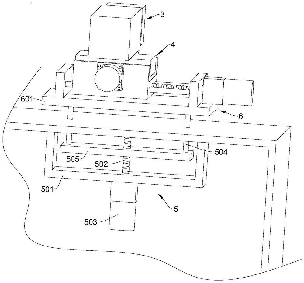
[0055] Z to the regulating mechanism 5 includes t...


PUM


Abstract

The invention relates to the technical field of capacitor manufacturing equipment, and provides a metallized film capacitor winding machine laser metal layer removing device which comprises a winding machine provided with a winding mechanism and at least one unwinding mechanism, and a laser removing device arranged between the winding mechanism and the unwinding mechanism. The device is used for removing a metal layer on the surface of a film in the film winding and unwinding process and comprises a Y-direction adjusting mechanism used for adjusting the position of the laser removing device in the film width direction. And the Z-direction adjusting mechanism is used for adjusting the position of the laser removing device in the film thickness direction. The device can adapt to metalized films with different widths and different thicknesses, and the applicability is improved.

Description

Technical field [0001] The present invention involves the field of capacitor manufacturing equipment technology. Specifically, it involves a metal -based thin film capacitor curling to remove the metal layer device. Background technique [0002] In the wound metal film capacitors manufacturing industry, the traditional curd device of the metal layer of the rolling equipment is composed of two aluminum foil. When the actual clearance is cleared, the two aluminum foil is pressed on the metalized film. Two two. An aluminum foil is conducted as a positive and negative electrode, and the arc burned metal layer is generated in the negative aluminum foil through the low voltage and large current to achieve the purpose of removing the metal layer. There are incomplete removal of this method; metallic film and two aluminum foils will produce relatively friction and are prone to vertical damage to effective metal membrane plating. The positive aluminum foil only takes advantage of conducti...

Claims


Application Information

Patent Timeline
IPC IPC(8): H01G13/06H01G13/02
CPCH01G13/06H01G13/02
Inventor 尹维佳谢静
Owner SICHUAN ZHONGXING ELECTRONICS
Learn More