
High-speed protection method suitable for T-connection type sending-out line of new energy station and application of high-speed protection method

A technology for sending out lines and new energy, applied in emergency protection circuit devices, circuit devices, components of emergency protection devices, etc. The effect of increasing the protection speed

Pending Publication Date: 2022-08-09
NORTH CHINA ELECTRIC POWER UNIV (BAODING) +2
View PDF14 Cites 0 Cited by
  • Summary
  • Abstract
  • Description
  • Claims
  • Application Information

AI Technical Summary

Problems solved by technology

[0008] Based on the above defects, we propose this high-speed protection method suitable for T-connection transmission lines of new energy stations, which reduces the amount of data required for communication through compressed sensing and relieves communication pressure; measures the fault characteristics on both sides of the line through the Canberra distance, The high-speed protection principle applicable to the T-connection transmission line of the new energy station is proposed, which effectively solves the problem of the performance degradation of the differential protection operation of the new energy access grid. The technical scheme is as follows:

Method used


Image

  • High-speed protection method suitable for T-connection type sending-out line of new energy station and application of high-speed protection method
  • High-speed protection method suitable for T-connection type sending-out line of new energy station and application of high-speed protection method
  • High-speed protection method suitable for T-connection type sending-out line of new energy station and application of high-speed protection method

Examples


Embodiment 1

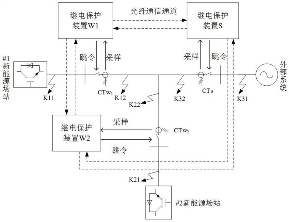
[0050] according to figure 1 The topology structure in the real-time digital simulator (Real time digital simulator, RTDS) builds the electromagnetic transient model of the new energy T-connected grid-connected system to verify the protection algorithm proposed by the present invention. The #1 new energy station in the figure is a double-fed The wind farm, #2 new energy station is a permanent magnet wind farm, and the two wind farms are connected to the grid through the T-connection transmission line. The capacity of the two wind farms is 99MW, the length of each line is 20km, the voltage level is 220kV, the positive and negative sequence impedances of the lines are 0.076+j0.338Ω / km, and the zero-sequence impedance is 0.284+j0.824Ω / km. The rated capacity of the main transformer is 120MVA, the transformation ratio is 220kV / 35kV, YNd wiring, and the short-circuit impedance is 6%.

[0051] The fault location is set as the fault outside the near-end area and the fault in the midp...


PUM


Abstract

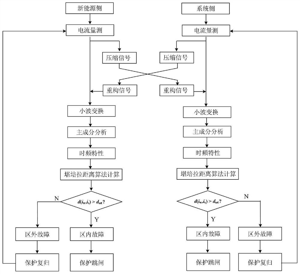
The high-speed protection method suitable for the new energy station T-connection type sending-out line comprises the following steps: aiming at the new energy station T-connection type sending-out line, installing the same protection device on each section of line, measuring the three-phase current of the side, carrying out compressed sensing on the three-phase current of the side to obtain a compressed signal, and transmitting the compressed signal to the other two sides through an optical fiber channel, the compressed signal is decompressed to obtain a reconstructed current after being received; the protection device superposes the three-phase short-circuit current of the two new energy stations, Morl et complex wavelet transform is carried out on the superposed current of the new energy stations and the system side current to obtain a wavelet coefficient matrix, and dimensionality reduction is carried out on the wavelet coefficient matrix by using a principal component analysis method to obtain a feature matrix; and each set of protection device carries out a Kanbalah distance criterion operation on the new energy superimposed current characteristic matrix and the system side current characteristic matrix, identifies a fault type by comparing a magnitude relationship between a criterion actual operation value and a setting value, and then starts a corresponding protection measure according to the fault type.

Description

technical field [0001] The invention relates to a protection method, in particular to a high-speed protection suitable for a T-connected outgoing line of a new energy station and its application. Background technique [0002] With the intensification of energy shortage and environmental pollution, new energy power generation has become one of the main ways to solve this problem. In order to save investment in power equipment, new energy power sources are often connected to the grid through T-connection transmission lines. However, due to the limited amplitude, frequency offset, phase angle controlled distortion, and non-fundamental frequency and low-order harmonics of new energy power supplies, the traditional differential protection as one of the main protections faces great challenges. . Therefore, it is necessary to study a new protection principle suitable for the T-connected outgoing line of new energy stations. [0003] Aiming at the problem that the performance of ...

Claims


Application Information

Patent Timeline
IPC IPC(8): H02H7/26H02H7/28H02H1/00
CPCH02H7/261H02H7/28H02H1/0007H02H1/0069Y04S40/124
Inventor 贾科温志文余磊孔繁哲张旸钮厚敏毕天姝郭小江申旭辉赵瑞斌巴蕾
Owner NORTH CHINA ELECTRIC POWER UNIV (BAODING)
Learn More