
Resonators for high power high temp. superconducting devices

A superconducting resonator, high temperature superconducting technology, applied in resonators, waveguide devices, electrical components and other directions

Inactive Publication Date: 2004-05-12
EI DU PONT DE NEMOURS & CO
View PDF0 Cites 0 Cited by
  • Summary
  • Abstract
  • Description
  • Claims
  • Application Information

AI Technical Summary

Problems solved by technology

However, coupling occurs only between adjacent resonators

Method used


Image

  • Resonators for high power high temp. superconducting devices
  • Resonators for high power high temp. superconducting devices
  • Resonators for high power high temp. superconducting devices

Examples


example

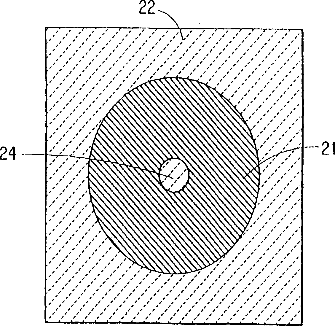
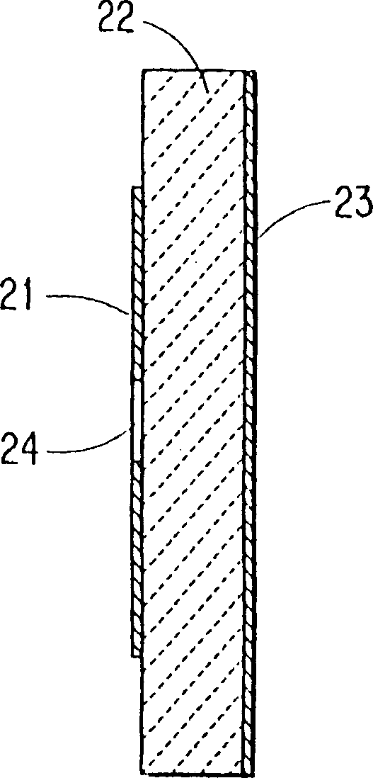
[0050] by LaAlO at 40.8mm x 17.2mm x 0.508mm 3 Deposit double-sided Tl on both sides (two levels) of the substrate 2 Ba 2 CaCu 2 o 8 HTS thin film, preparation of high power triode TM 010 modulo HTS filter. Using standard double-sided photolithography processing and ion beam milling, prepare filters with the structures shown in Figures 9(a) and 9(b), where 90 is a substrate; 91a and 91b are octagonal resonators; 92 is An octagonal resonator with a central hole 93 thereon; 94 is a ground plate; opening 95a, coplanar centerline 96a and T-shaped coupling branch 97a together form an input coupling circuit; opening 95b, coplanar centerline 96b Together with the T-shaped coupling branch line 97b, an output coupling circuit is formed; openings 98a and 98b form an internal resonator coupling circuit.

[0051] The filter was encased in a copper housing with SMA-compatible input and output connectors, and the filter was tested at 77K. The diameter of the central hole 93 in the r...


PUM


Abstract

TM0i0 mode (i = 1, 2, 3 ...) planar high temperature supercondutor resonators useful in high temperature superconducting filters, filter banks and multiplexers comprise a shaped high temperature superconductor film and a high temperature superconductor ground plate deposited on opposite sides of a dielectric substrate, wherein the shaped high temperature superconductor film has an aperture in the center thereof and has a shape selected from the group consisting of circles and polygons.

Description

technical field [0001] The invention relates to a TM having a hole in its center 0i0 Mode (i=1, 2, 3, . . . ) circular and polygonal planar high temperature superconducting resonators. Background technique [0002] Filter banks and signal multipliers are widely used in communications as channelizers that separate or combine input signals according to their frequencies. The basic building block of filter banks and signal multipliers is the filter, which consists of multiple resonators as frequency selective elements. For use in communications, filters need to have narrow bandwidth, precise center frequency, low insertion loss in-band, high rejection off-band, steep edges at band edges, compact size and high power usage capability. Common filters made from conventional conductors are not suitable for communication use due to the high losses on conventional conductors. [0003] High-temperature superconducting (HTS) planar filters have excellent performance at low power. Se...

Claims


Application Information

Patent Timeline
Patent Type & Authority Patents(China)
IPC IPC(8): H01P1/203H01P7/08
CPCH01P7/082H01P7/08
Inventor 沈致远
Owner EI DU PONT DE NEMOURS & CO
Learn More