Detecting system and method for lack of lens

A lens and detector technology, applied in the field of lack of lens detection system and method, can solve the problems of effective software and high cost, etc.

Inactive Publication Date: 2004-08-04
JOHNSON & JOHNSON VISION CARE INC
View PDF6 Cites 1 Cited by
  • Summary
  • Abstract
  • Description
  • Claims
  • Application Information

AI Technical Summary

Problems solved by technology

Even though the method works relatively well, it is expensive and the software needs to be very effective

Method used


Image

  • Detecting system and method for lack of lens
  • Detecting system and method for lack of lens
  • Detecting system and method for lack of lens

Examples


Embodiment Construction

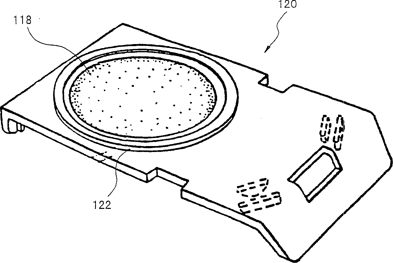
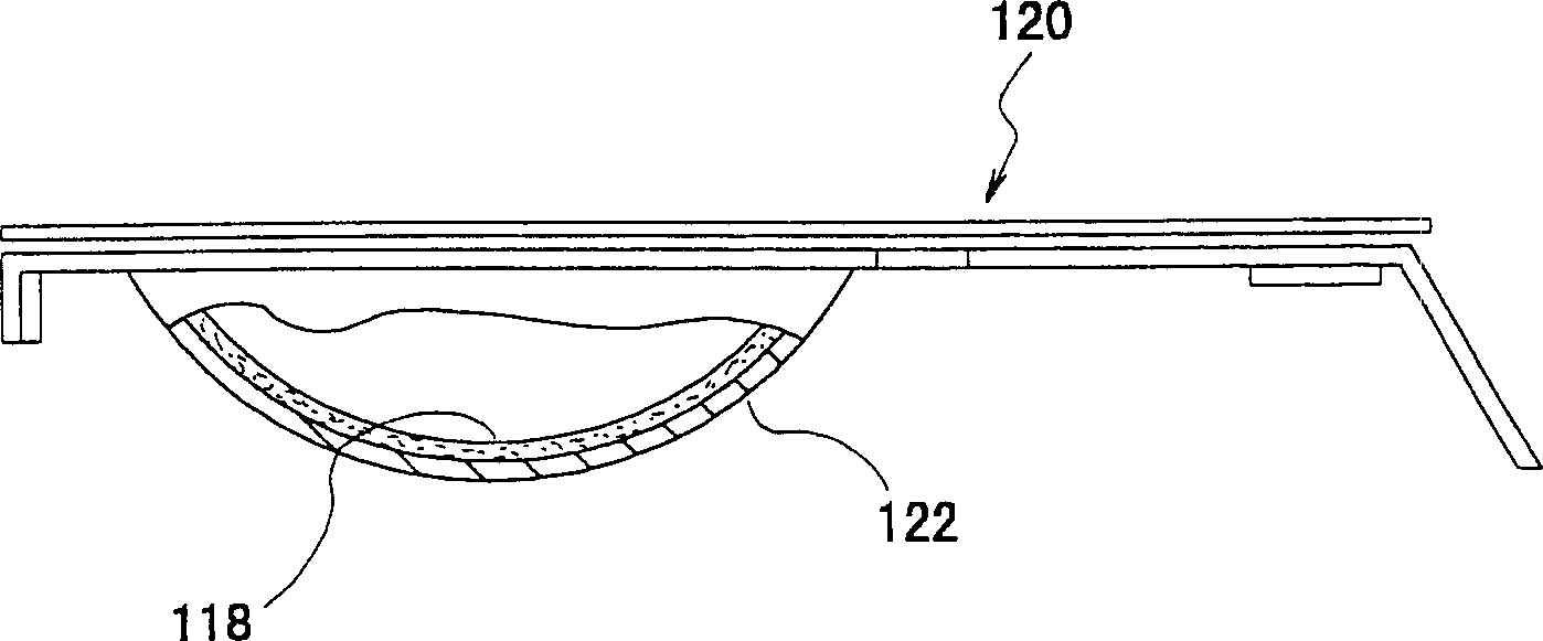
[0037] The term "holder" as used herein refers to a support container for a lens. Generally, the support is a blister component composed of a base (such as a bowl) and a cover (such as a lidstock). The cover can be, for example, a transparent plastic cover or foil-coated plastic. The term "support" here also denotes a base body without a cover.

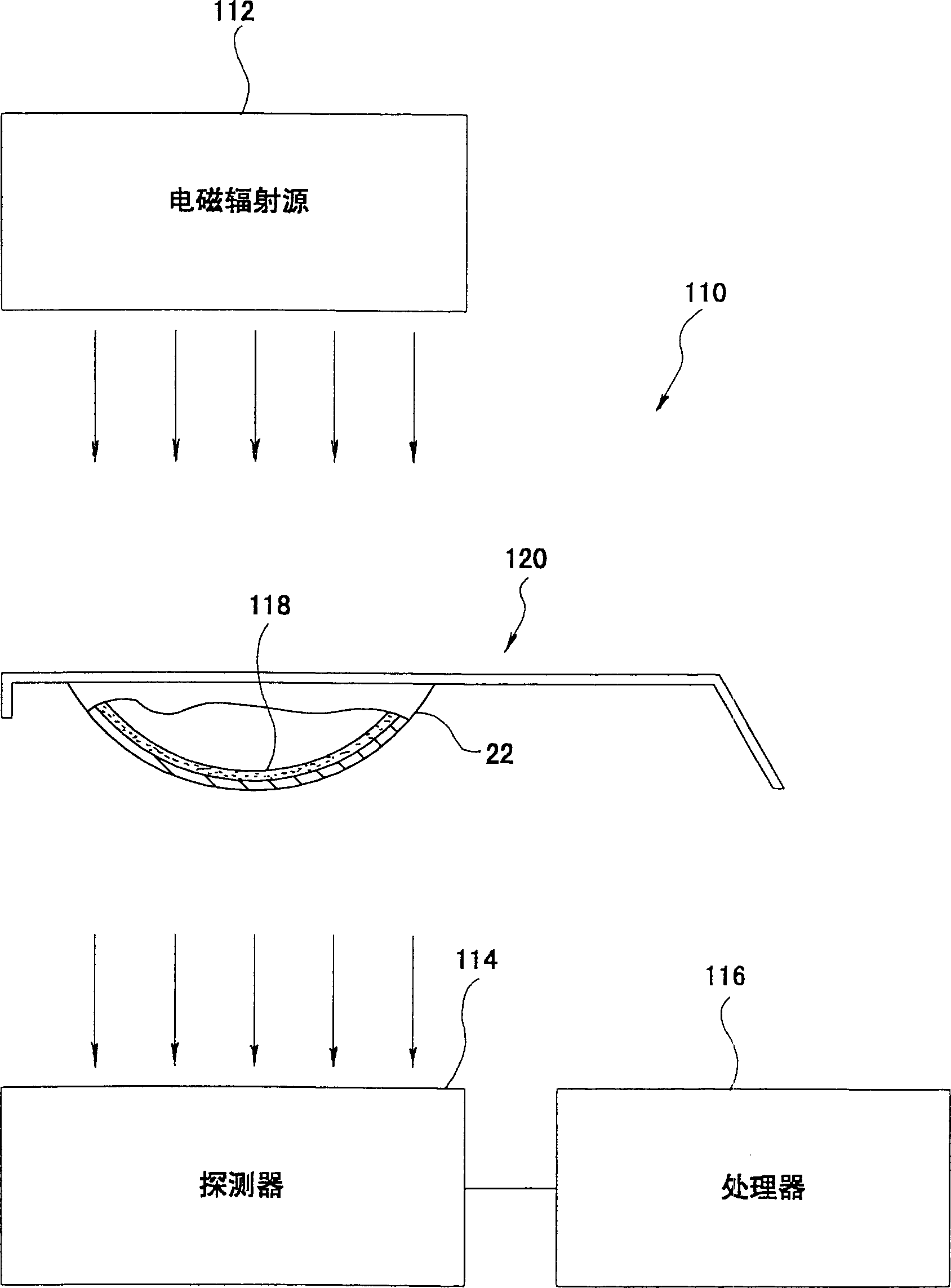
[0038] figure 1 The lack of lens detection means is shown in , which means is indicated by reference numeral 110 . The detection device 110 includes an electromagnetic radiation source 112 , a detector 114 and a processor 116 . Radiation source 112 may be a broadband radiation source that emits ultraviolet, visible and infrared light. For example, a visible light source like the Phillips photothermal bulb P / NPL-S9W / 10 emits electromagnetic radiation in the ultraviolet band. Alternatively, the radiation source 112 may generate electromagnetic radiation in a narrow frequency band, or the radiation source 112 may be combined with a ...


PUM

PropertyMeasurementUnit
wavelengthaaaaaaaaaa

Abstract

A system for determining the presence and optionally the position of an ophthalmic product such as a contact lens in a container is provided.

Description

[0001] This application is a continuation of US Patent Application No. 09 / 187,579 filed November 5, 1998 by Ross and Newton, which has the same subject matter as this application and is incorporated herein by reference. technical field [0002] The present invention relates to a system for detecting the presence and optionally the position of a product within a holder or assembly, and more particularly, the present invention relates to an apparatus for verifying the presence of an ophthalmic product, such as a contact lens, within a holder and methods. Background technique [0003] An automated system that can be used to manufacture ophthalmic products has been disclosed in US Patent 5,080,839. These systems have reached a very high degree of automation. The lens is molded, then released from the mold, further processed, and then assembled, all without human intervention. However, even with a highly automated system, a human visual inspection of each assembly is required t...

Claims


Application Information

Patent Timeline
Patent Type & Authority Patents(China)
IPC IPC(8): G01V8/00B65B25/00B65B57/10G01N21/95
CPCB65B57/10B65B25/008G01N21/9508G01V8/00
Inventor D·F·罗斯三世T·P·纽顿J·A·埃贝尔P·德科尔蒂R·L·西蒙斯M·F·维德曼
Owner JOHNSON & JOHNSON VISION CARE INC
Why Eureka
Try Eureka