Eureka AIR delivers breakthrough ideas for toughest innovation challenges, trusted by R&D personnel around the world.

Optical modulator with pre-determined frequency chirp

An optical modulator and optical technology, applied in optics, nonlinear optics, instruments, etc., can solve the problem of non-intrinsic alignment of modulation electrodes

Inactive Publication Date: 2004-12-15
BOOKHAM TECH
View PDF0 Cites 0 Cited by
  • Summary
  • Abstract
  • Description
  • Claims
  • Application Information

AI Technical Summary

Problems solved by technology

This technique of generating chirp is only suitable for modulators where the modulating electrode is not inherently fixedly aligned with the optical waveguide, and is therefore not suitable for GaAs modulators where the fabrication process The reason electrodes and waveguides are inherently aligned

Method used


Image

  • Optical modulator with pre-determined frequency chirp
  • Optical modulator with pre-determined frequency chirp
  • Optical modulator with pre-determined frequency chirp

Examples


Embodiment Construction

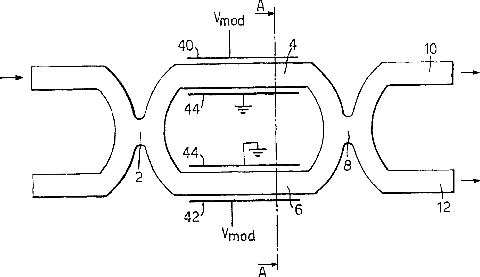
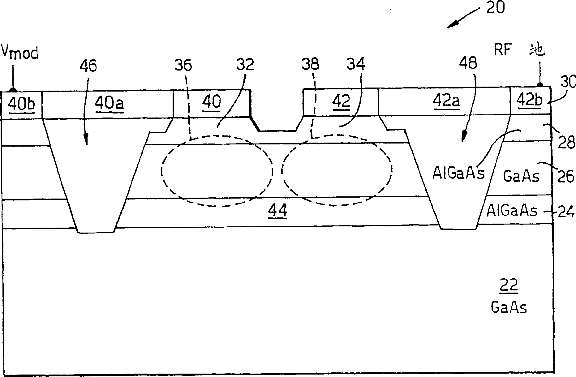
[0053] To facilitate understanding of the optical modulator of the present invention, a known Mach-Zehnder optical modulator fabricated in GaAs / AlGaAs is first described. in the attached figure 2 shown in the accompanying figure 1 The "AA" section is the end view of this modulator. The optical modulator 20 comprises, in order, an undoped (semi-insulating) gallium arsenide (GaAs) substrate 22, a conductively doped n-type aluminum gallium arsenide (AlGaAs) layer 24, a deeper undoped arsenide gallium chloride layer 26 , a deeper undoped AlGaAs layer 28 and a conductive metal layer 30 . GaAs layer 26 provides an optical waveguide medium with a contrast in refractive index between AlGaAs layers 24 and 28 , and GaAs layer 26 provides vertical confinement, thereby confining light propagating within layer 26 . The optical waveguide arm of the modulator (4, 6, see appendix figure 1 ) is defined in the GaAs layer 26, and the GaAs layer 26 is selectively etched on the two mesas (ste...


PUM


Abstract

An optical modulator for producing a modulated optical output having a pre-determined frequency chirp comprises: optical splitting means for receiving and splitting an optical input signal to be modulated into two optical signals to pass along two waveguide arms (36, 38) made of electro-optic material; and optical combining means for receiving and combining the two optical signals into said modulated optical output. At least one electrode pair (40 / 44, 42 / 44) is associated with each waveguide arm (36, 38), and is electrically connected in series such as to modulate the phase of said optical signals in antiphase in response to a single electrical signal (Vmod) applied thereto. The modulator is characterised by a capacitive element (60) connected to the electrode pair (42) of one arm (38) such as to modify the division of the single electrical signal (Vmod) such that the magnitude of the electrical signal across the electrode pair (42 / 44) of one arm (38) is different to that across the electrode pair (40 / 44) of the other arm (36) thereby imparting the pre-determined frequency chirp in the modulated optical output.

Description

technical field [0001] The present invention relates to an optical modulator with a predetermined frequency chirp, and more particularly, to (but not limited to) a π-electro-optic Mach- Zehnder optical modulators or directional couplers. Background technique [0002] As is well known, dispersion is a fundamental property of any waveguide medium, such as optical fibers used in optical communication systems. Dispersion causes different wavelengths to travel at different speeds due to the properties of the material medium and the waveguide mechanism. [0003] In a communication system, most fundamentally, the carrier of a digital or analog data stream to be communicated is modulated to divide the frequency of the carrier into one or more sidebands. Thus dispersion in longer fibers distorts the data progressively over distance as the sidebands are phase-shifted from each other. Chromatic dispersion has the effect of broadening or spreading the data pulses, and this effect lim...

Claims


Application Information

Patent Timeline
Patent Type & Authority Patents(China)
IPC IPC(8): G02F1/01G02F1/015G02F1/025G02F1/03G02F1/21G02F1/225
CPCG02F1/225G02F1/0123G02F1/2255G02F2203/25G02F1/2257G02F2001/212G02F1/212
Inventor R·G·沃克尔
Owner BOOKHAM TECH
Why Eureka
Eureka Blog
Learn More