
Driving method of display device and its driving circuit

A technology of a display device and a driving method, which is applied to static indicators, cathode ray tube indicators, instruments, etc., can solve the problems of reducing power consumption and the inability of display devices to correspond

Inactive Publication Date: 2005-01-05
SANYO ELECTRIC CO LTD
View PDF0 Cites 0 Cited by
  • Summary
  • Abstract
  • Description
  • Claims
  • Application Information

AI Technical Summary

Problems solved by technology

However, even during power saving, there may be a demand for displaying at an arbitrary position or displaying an arbitrary figure, but a display device that individually controls a pre-divided display area cannot meet this demand.
[0006] In addition, depending on the type of equipment equipped with a display device, the display content and display position requirements during power saving are different, so the structure of the display panel and the drive circuit must be developed separately as needed.
[0007] If it is a matrix type display device, then although any display can be performed at any position, in the power-saving display, even if only a part of the graphics is displayed, since the other areas also need normal driving, it is not necessary to No power reduction effect from partial display

Method used


Image

  • Driving method of display device and its driving circuit
  • Driving method of display device and its driving circuit
  • Driving method of display device and its driving circuit

Examples


Embodiment Construction

[0076] Hereinafter, preferred embodiments of the present invention (hereinafter referred to as embodiments) will be described using the drawings.

[0077] basic structure

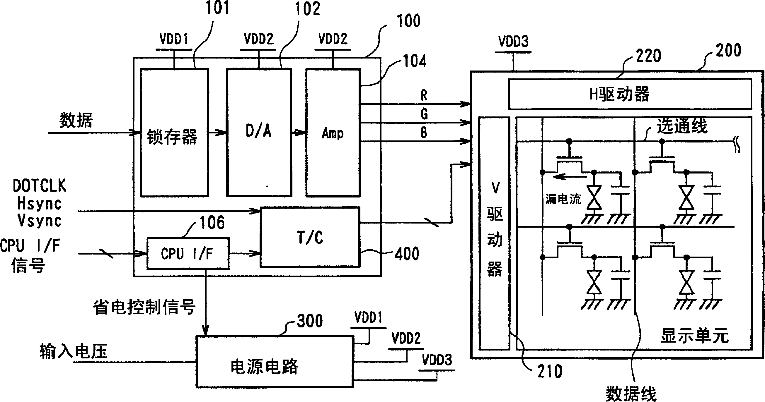
[0078] figure 1 The schematic structure of the display device of this invention is shown. The display device is, for example, a flat-panel display device such as an LCD mounted in a mobile phone, and includes a liquid crystal display (LCD) panel 200 formed by sealing liquid crystals in a pair of substrates, a drive circuit 100 for driving the LCD panel 200, and a drive circuit 100 And the LCD panel 200 supplies the necessary power supply voltage (for example, ADD1, ADD2, ADD3) to the power supply circuit 300.

[0079] The LCD panel 200 is an active matrix type panel, in which a thin film transistor is provided as a switching element in each pixel, and the on / off of the thin film transistor is controlled by a gate line extending along the row direction, and through the thin film transistor By supplying di...


PUM


Abstract

In the driving of a liquid crystal display panel with pixels in a matrix comprising n rows and m columns, when a partial display instruction is issued, respective rows in a display area (202) of s rows and m columns within the matrix are sequentially selected for one frame. Then, predetermined partial display data is written into the selected rows. Predetermined background data such as white display data is written into the background area (204) other than the partial display area (202). Reliably reversely drive the pixels of the background section by background dispalyed data.

Description

technical field [0001] The present invention relates to a driving method and a driving circuit of a plane display device such as a liquid crystal display device, in particular to a partial display thereof. Background technique [0002] Flat panel display devices such as liquid crystal display devices or organic EL display devices are light, thin, and low in power consumption, so they are suitable as display devices for portable devices such as mobile phones, and are used in many portable devices. [0003] This display device is known to have a matrix type display device capable of displaying arbitrary graphics through a plurality of pixels arranged in a matrix shape, a step type display device displaying fixed graphics such as a clock, and a matrix type display device and a step type display device installed in the same display panel. type of display device, etc. [0004] However, further reduction in power consumption is required in portable devices, and further reduction ...

Claims


Application Information

Patent Timeline
Patent Type & Authority Patents(China)
IPC IPC(8): G09G3/36G09G5/02
CPCG09G2310/04G09G3/3677G09G2320/043G09G5/024G09G3/3688G09G2330/021G09G3/3648G09G2310/0248G09G3/36
Inventor 筒井雄介北川诚小林贡上原久夫藤冈诚
Owner SANYO ELECTRIC CO LTD
Learn More