Cable reel

A cable reel and cable technology, applied in the field of robot applications, can solve the problems of poor reliability, heavy weight, and high cost, and achieve the effect of reducing weight and cost, reducing mechanism complexity, and better effect

Inactive Publication Date: 2005-02-02
SHANGHAI JIAO TONG UNIV
View PDF0 Cites 0 Cited by
  • Summary
  • Abstract
  • Description
  • Claims
  • Application Information

AI Technical Summary

Problems solved by technology

Common cable reels are plug and play, such as the cable reels produced by Yangzhou Huatai Cable Plate Factory (http: / / www.cable-plate.com), you must put the wires in place before plugging in the power plug (otherwise , with the rotation of the cable reel, there will be cable winding), which brings great inconvenience to practical applications, and this kind of cable reel can only be used for power cables, and cannot transmit control, data, sound and other signals, so This kind of cable reel cannot be used in the field of mobile robots
Through literature search, it is found that American Remotec Corporation (URL http: / / www.remotec-andros.com ) A slip ring is added to the cable reel used in the risk-removing robot, which solves the problem of cable winding, and it can transmit data, voice and other signals, which greatly promotes the development of cable communication of mobile robots, but in the actual application process Among them, it also has many shortcomings: 1. The structure is relatively complicated, the cost is high, and the weight is heavy; 2. The slip ring transmits power or signals by contact, which is susceptible to interference and poor reliability, especially for image signals. Larger; 3. Using optical fiber communication, the quality is good and free from interference, but the optical fiber signal cannot pass through the slip ring, and the optical signal can only be converted into an electrical signal before the slip ring, which reduces the advantages of optical fiber

Method used


Image

  • Cable reel
  • Cable reel

Examples


Embodiment Construction

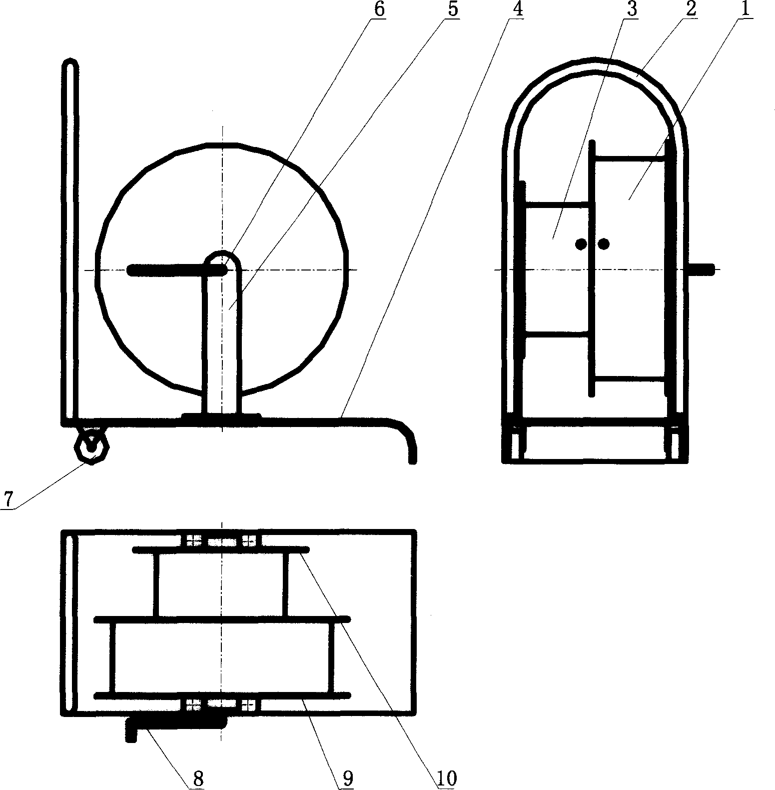
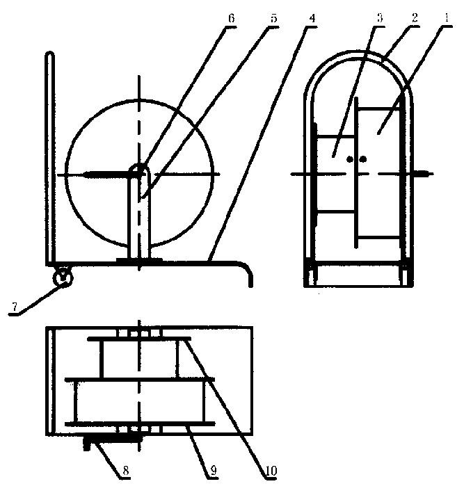
[0008] Such as figure 1 As shown, the present invention comprises: big roller barrel 1, hand-held push handle 2, small roller barrel 3, underframe 4, axle support 5, axle 6, underframe walking small wheel 7, rocking arm 8, big roller wall 9, small Roller wall 10. The connection method is as follows: the large roller wall 9 and the small roller wall 10 are respectively fixed on the axle 6, the large roller cylinder 1 is fixed between the two large roller walls 9 with the axle 6 as the axis, and the small roller cylinder 3 is also fixed on the axle 6. For the axle center is fixed between the big roller wall 9 and the small roller wall 10, then the big roller cylinder 1, the small roller cylinder 3, the large roller wall 9, and the small roller wall 10 can rotate together with the axle 6, and the rocking arm 8 and the axle 6 are connected together, the rocker arm 8 is the input source of power, the wheel shaft 6 is supported on the chassis 4 through the wheel shaft bracket 5, t...


PUM


Abstract

The present invention relates to the field of robot application technology. The cable holder includes large roller, hand pushing handle, small roller, chassis, wheel shaft support, wheel shaft, small walking wheels, rocker, large roller walls and small roller wall. The large roller walls and small roller wall are fixed onto the wheel shaft separately, the large roller with the wheel shaft as shaft is fixed between two large roller walls, the small roller with the wheel shaft as shaft is fixed between the large roller wall and the small roller wall, the rocker is connected to the wheel shaft, the wheel shaft is supported on the chassis via its support, the small walking wheels are set below the chassis, and the hand pushing handle is set on the chassis. The present invention has no slip rings, and this results in less complexity, less weight, low cost and continuous signal transmission.

Description

technical field [0001] The invention relates to a cable reel, in particular to a cable reel for a mobile robot, belonging to the technical field of robot applications. Background technique [0002] Cable reels are widely used in electrical and mechanical fields, especially in the field of mobile robots. Although wireless remote control technology is relatively mature now, it has become the biggest bottleneck in the application of mobile robots due to its low reliability. Therefore, cable communication still occupies a very important position in the field of mobile robots. For cabled communication, the cable reel is an essential accessory. Common cable reels are plug and play, such as the cable reels produced by Yangzhou Huatai Cable Plate Factory (http: / / www.cable-plate.com), you must put the wires in place before plugging in the power plug (otherwise , with the rotation of the cable reel, there will be cable winding), which brings great inconvenience to practical applica...

Claims


Application Information

Patent Timeline
Patent Type & Authority Patents(China)
IPC IPC(8): B65H75/42
Inventor 乔凤斌刘淼杨汝清赵维江
Owner SHANGHAI JIAO TONG UNIV
Why Eureka
Try Eureka