Supercharge Your Innovation With Domain-Expert AI Agents!

Wafer atmospheric transport module having controlled mini-environment

A manufacturing method, atmospheric pressure technology, applied in the direction of conveyor objects, semiconductor/solid-state device manufacturing, electrical components, etc., can solve problems such as residue, mental confusion, and difficult cleaning

Inactive Publication Date: 2005-02-16
LAM RES CORP
View PDF1 Cites 2 Cited by
  • Summary
  • Abstract
  • Description
  • Claims
  • Application Information

AI Technical Summary

Problems solved by technology

The problem that the gas 166 that exists between wafer 162 brings is: this chemical gas may continue its chemical reaction under certain circumstances, and causes the yield of processed wafer 162 to decline
Potential financial losses associated with reduced yield can be significant if wafer quality degradation is greater
[0008] Another problem brought about by the stagnant wafer cassette environment 152b is that any particles that may have fallen on the surface of the wafer 162 will continue to remain on the wafer while the wafer cassette is parked in the wafer cassette environment 152b. surface
The longer the particles remain on the surface of the wafer 162, the more likely the particles are to cause damage to sensitive integrated circuits and the more difficult it is to clean.
[0009] Another problem with the wafer cassette 160 parked in the static environment 152b is that once a process engineer opens the door 155 to remove the wafer cassette 160, the wafer cassette 160 may expose the process engineer to potential exposure to Unsuitable levels of toxic gas 166
In some cases, the process engineer's exposure to the process gases and chemical by-products may cause the process engineer to become confused while handling the wafer cassette, thus making the wafer cassette 160 full of valuable processed semiconductor wafers 162 drop

Method used


Image

  • Wafer atmospheric transport module having controlled mini-environment
  • Wafer atmospheric transport module having controlled mini-environment
  • Wafer atmospheric transport module having controlled mini-environment

Examples


Embodiment Construction

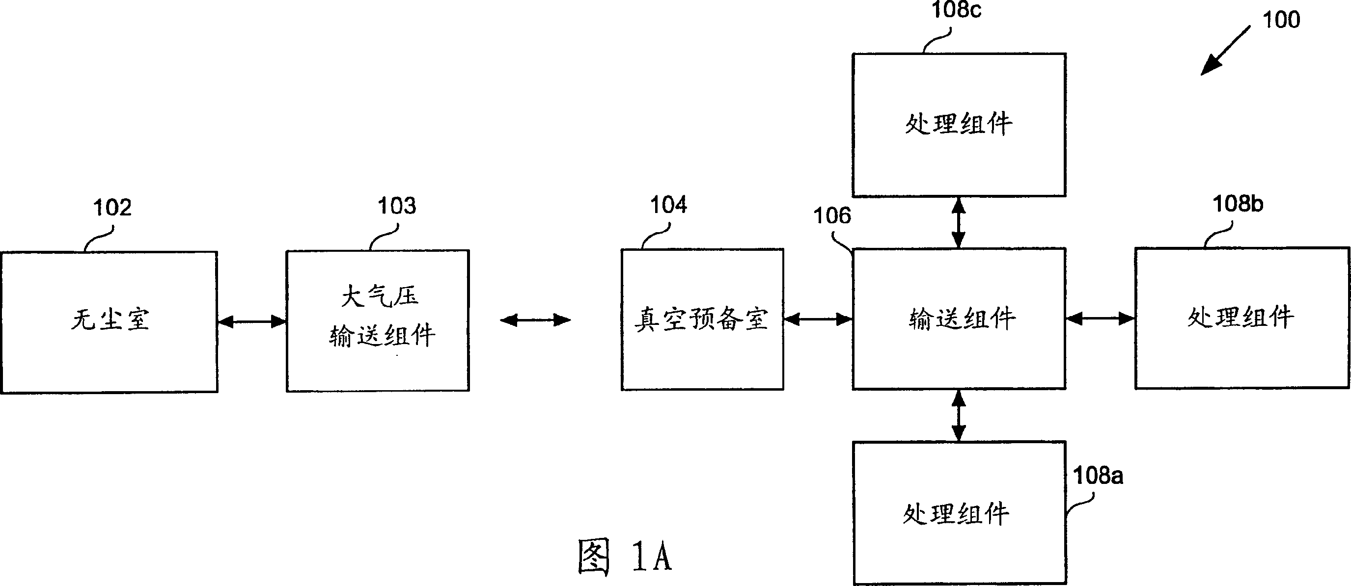
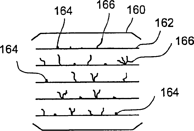
[0024] The present invention describes an atmospheric transport assembly that can create a miniaturized environment in the area where wafer cassettes are temporarily stored during processing. The compact environment preferably includes a gas flow through and substantially parallel to the wafers so that process gases and by-products can be substantially purged from between the wafers in the wafer basin. It will be apparent, however, to one skilled in the art that the present invention may be practiced without some or all of these specific details. In other words, well-known processing operations will not be described in detail here in order not to obscure the present invention.

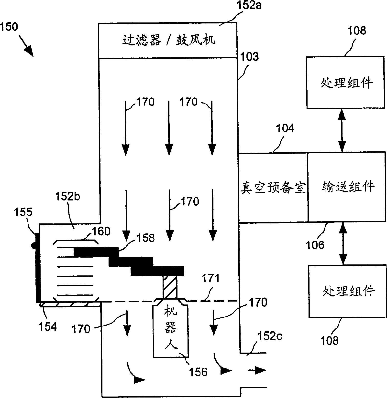
[0025] According to an embodiment of the present invention, Figure 2A An atmospheric transfer module (ATM) 200 is shown resting on a clean room floor 201 . The ATM 200 includes a top 200a having a filter and a variable speed blower. Alternatively, the variable speed blower may be a fixed speed blowe...


PUM


Abstract

An atmospheric transport module is provided. The module includes an enclosed housing having a top region, a central region, a bottom region, and a load cell region. A blower is located in the top region of the enclosed housing and is configured to generate a flow of air downward into the central region. A shelf in the load cell region defines a separation between the central region and the bottom region of the enclosed housing. The shelf is at least partially spaced apart from a wall of the load cell region to thereby define a slot behind the shelf. A perforated sheet is configured to extend horizontally from the shelf and further define the separation between the central region and the bottom region. In this example, air flow generated by the blower is restricted from freely flowing through the perforated sheet and is partially caused to be redirected toward the shelf of the load cell, through the slot and into the bottom region of the enclosure housing. A cassette having one or more wafers is configured to sit on the shelf in the load cell and thus be subjected to the redirected air flow. This redirected air flow will thus gently flow over the surfaces of the wafers and assist in removing post-process gases and particles from over the wafer surfaces while the wafers temporarily sit in the atmospheric transport module.

Description

technical field [0001] The present invention relates to the art of transferring wafers in an assembly of semiconductor processing equipment, and more particularly to an assembly having a controlled compact environment. Background technique [0002] In the manufacture of semiconductor devices, process chambers are interfaced with each other to allow transfer of wafers or substrates (eg, between connected process chambers). This transfer is via a transport assembly that moves the wafer through slots or openings provided in adjacent walls of the attached process chambers. For example, transport assemblies are often used in conjunction with various substrate processing assemblies, which may include semiconductor etch systems, material deposition systems, and flat panel display etch systems. As the requirements for cleanliness and high processing precision grow, so does the need to reduce human influence during and between the individual processing steps. This need has been par...

Claims


Application Information

Patent Timeline
Patent Type & Authority Patents(China)
IPC IPC(8): B65G49/07H01L21/02H01L21/677
CPCH01L21/67778H01L21/00
Inventor 法罗·F·凯维戴维·E·雅各布蒂恩·杰伊·拉森马汀·R·马拉钦
Owner LAM RES CORP
Features
  • R&D
  • Intellectual Property
  • Life Sciences
  • Materials
  • Tech Scout
  • Unparalleled Data Quality
  • Higher Quality Content
  • 60% Fewer Hallucinations
Learn More