Capacitive sensing apparatus for a vehicle seat

a sensing apparatus and vehicle seat technology, applied in the direction of instruments, apparatus for force/torque/work measurement, tractors, etc., can solve the problems of large development effort to determine optimal sensor placement for a given seat configuration, limited number of sensing elements, and limited overall resolution of the sensor pad, so as to reduce parasitic coupling and improve measurement resolution

Active Publication Date: 2007-05-15
APTIV TECH LTD
View PDF11 Cites 65 Cited by
  • Summary
  • Abstract
  • Description
  • Claims
  • Application Information

AI Technical Summary

Benefits of technology

[0005]The present invention provides an improved capacitive sensing apparatus for a vehicle seat including a deflectable dielectric mat and a flexible printed circuit that wraps around the major surfaces of the dielectric mat to define upper and lower conductor strips that overlap in a direction perpendicular to the dielectric mat. Overlapping regions of the conductor strips define an array of capacitive load cells distributed over the seating surface. A connector stub depending from the flexible printed circuit couples the conductor strips to an external circuit that measures the capacitance of the various load cells to determine occupant weight and weight distribution. The relatively small area of the overlapping conductor strip regions significantly reduces parasitic coupling between such regions and the seat pan, and the number of capacitive load cells for a given number of electrical interconnects is significantly increased for improved measurement resolution.

Problems solved by technology

While the capacitive sensing approach described in the aforementioned U.S. Pat. No. 6,927,678 to Fultz et al. can be very cost effective to manufacture and install, the number of sensing elements is limited by electrical connection costs.
As a result, the overall resolution of the sensor pad is similarly limited and the development effort to determine optimal sensor placement for a given seat configuration can be considerable.
Also, when the seat has a metallic cushion support pan, parasitic coupling between the lower metalized sensor film and the seat pan can introduce error in the capacitance measurements.

Method used


Image

  • Capacitive sensing apparatus for a vehicle seat
  • Capacitive sensing apparatus for a vehicle seat
  • Capacitive sensing apparatus for a vehicle seat

Examples


Embodiment Construction

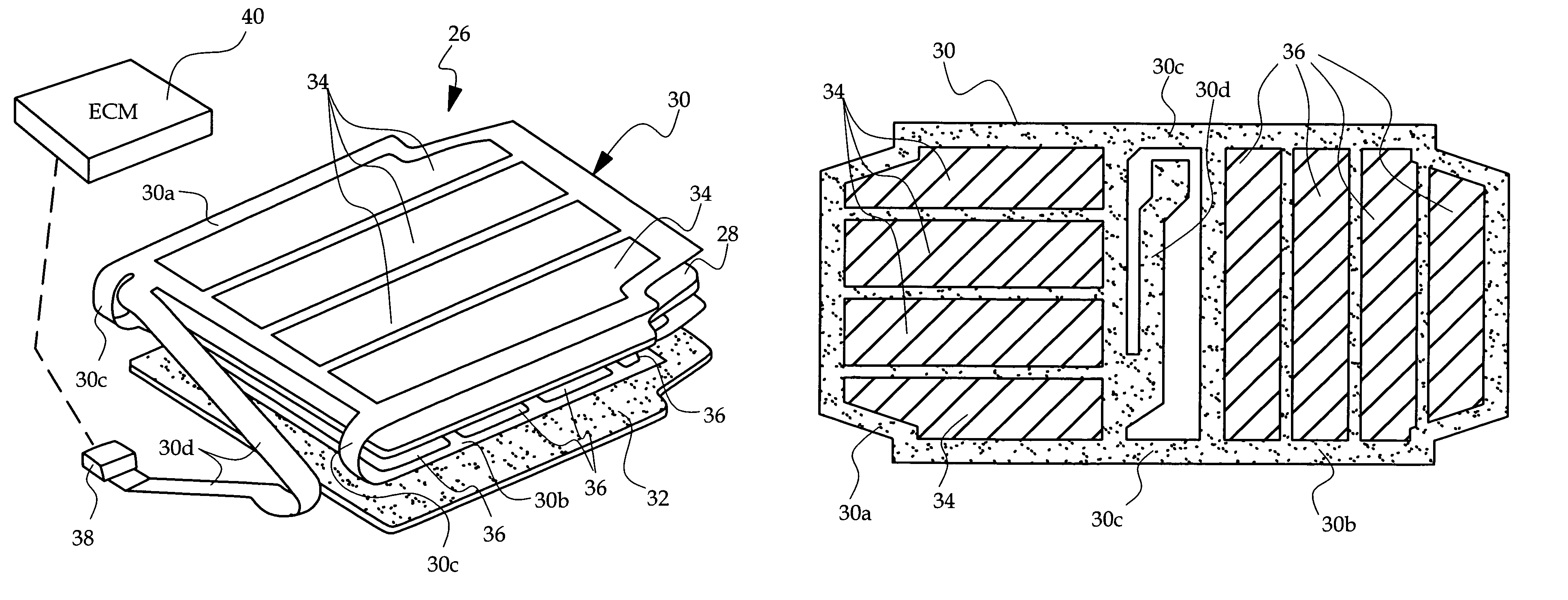
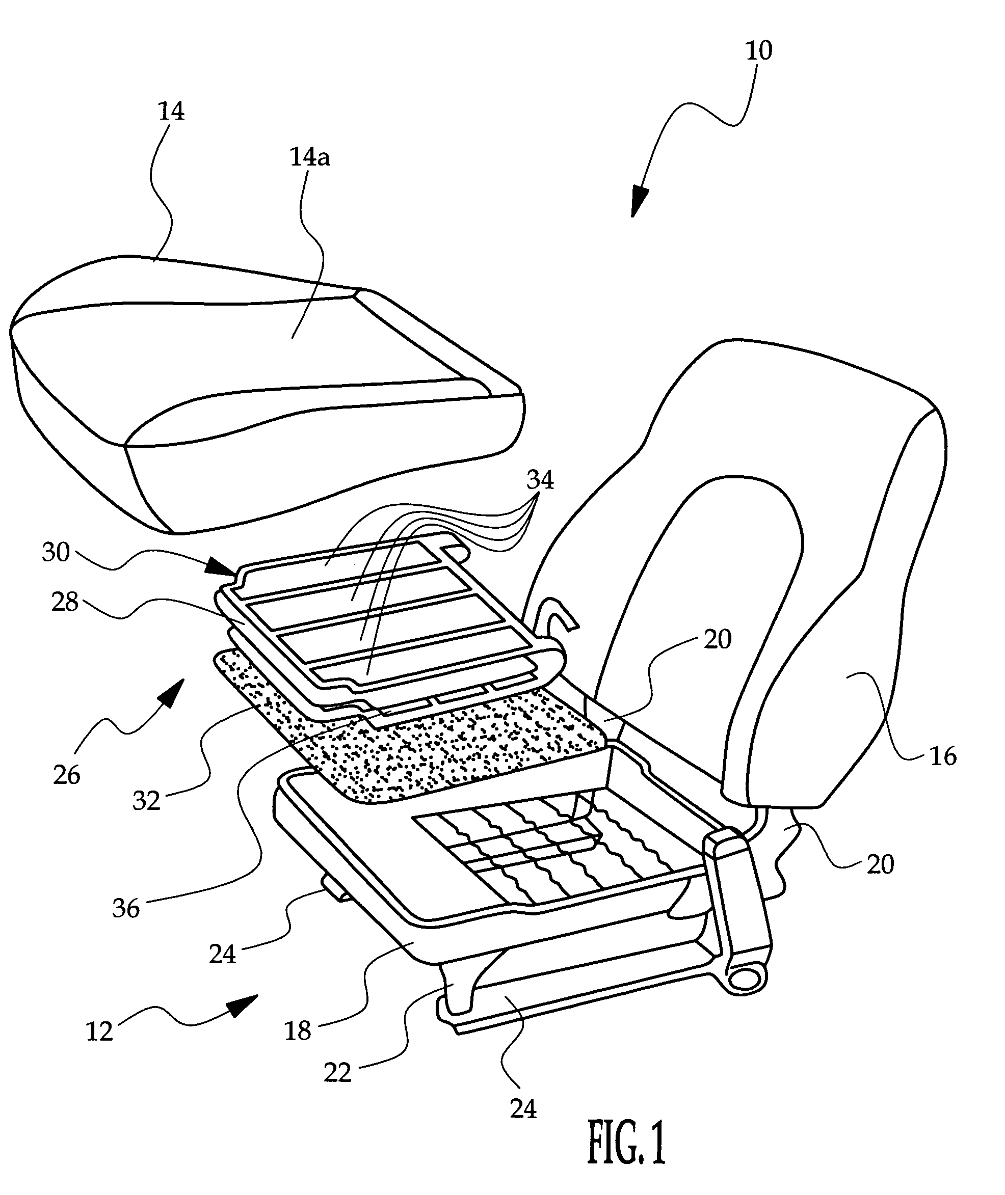
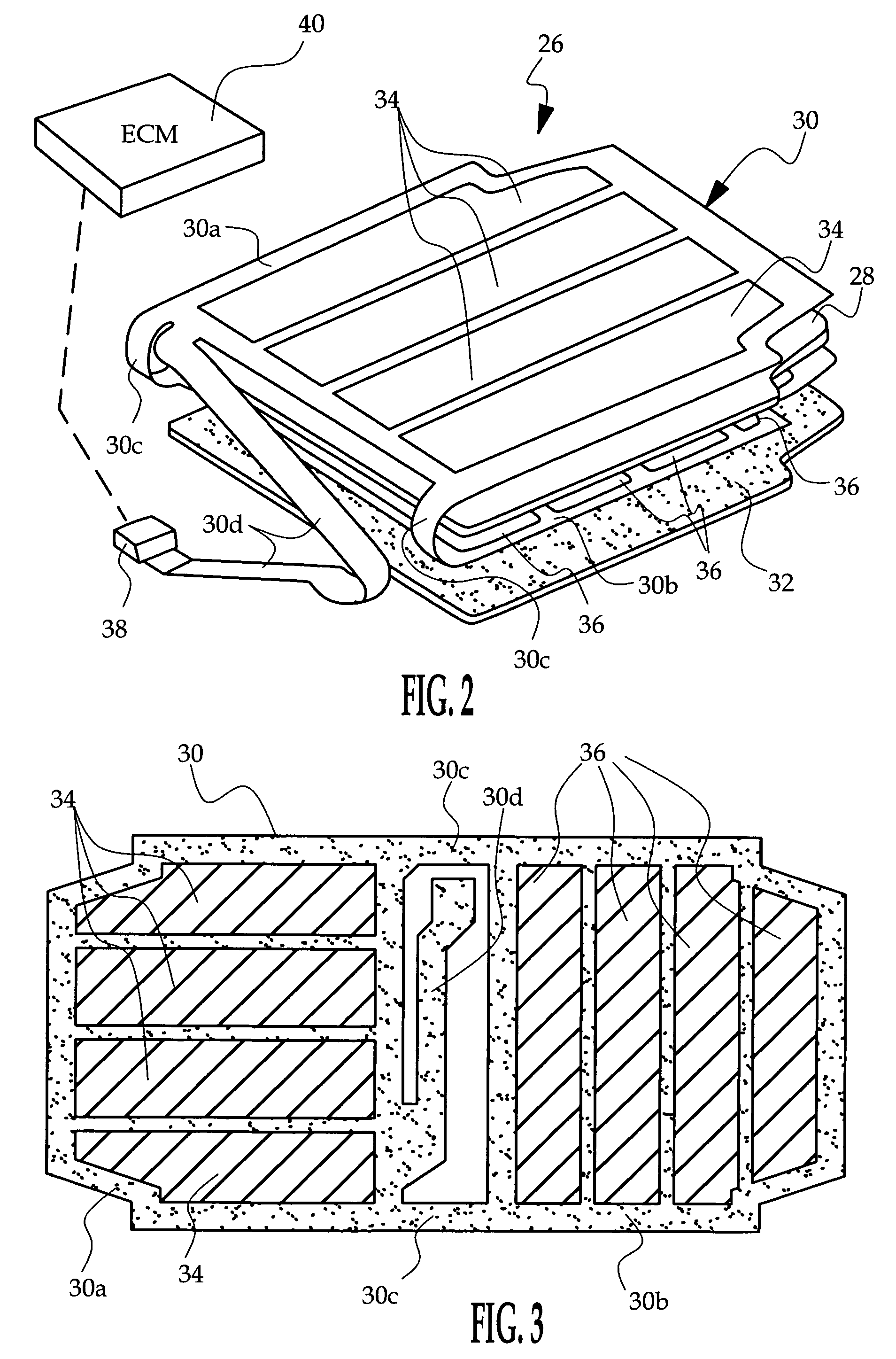
[0010]Referring to FIG. 1, the reference numeral 10 generally designates a vehicle seat equipped with a capacitive sensing apparatus according to this invention. The seat 10 includes a frame assembly 12, a bottom foam cushion 14 and a back foam cushion 16. The frame assembly 12 includes a metal seat pan 18 with integral spring suspension for supporting the bottom foam cushion 14, and a set of depending frame elements 20 for supporting the back foam cushion 16. A set of posts 22 attach the seat pan 18 to pair of tracks 24, which in turn, are secured to the floor of the vehicle. A capacitive sensor assembly 26 is sandwiched between the bottom cushion 14 and the seat pan 18 for the purpose of determining occupant weight and weight distribution, as explained below.

[0011]Referring to FIGS. 1–2, the capacitive sensor assembly 26 includes a dielectric mat 28, a flexible printed circuit 30, and a felt pad 32 disposed between the flexible printed circuit 30 and the seat pan 18. In the illust...


PUM


Abstract

A capacitive sensing apparatus for a vehicle seat includes a deflectable dielectric mat and a flexible printed circuit that wraps around the major surfaces of the dielectric mat to define upper and lower conductor strips that overlap in a direction perpendicular to the dielectric mat. Overlapping regions of the conductor strips define an array of capacitive load cells distributed over the seating surface. A connector stub depending from the flexible printed circuit couples the conductor strips to an external circuit that measures the capacitance of the various load cells to determine occupant weight and weight distribution.

Description

TECHNICAL FIELD[0001]The present invention related to a capacitive sensing apparatus for vehicle seat occupant classification and weight estimation.BACKGROUND OF THE INVENTION[0002]Seat occupant detection systems are commonly in connection with air bags and other pyrotechnically deployed restraints as a means of judging whether, and how forcefully, to deploy the restraint. It has been shown that the seated weight of the occupant in combination with the weight distribution over the seating area can be used to reliably classify the occupant for purposes of restraint deployment. For example, normal energy deployment can be enabled for adults, reduced energy deployment can be enabled for a seated child, and deployment can be disabled entirely for a child seat or infant seat.[0003]Of the various ways that have been devised for determining the seated weight and weight distribution of an occupant, perhaps the most simple and cost-effective involves installing a multi-sensor pad in or under...

Claims


Application Information

Patent Timeline
Patent Type & Authority Patents(United States)
IPC IPC(8): B60R21/015G01G3/12
CPCB60N2/002B60R21/01516B60R21/01532G01L1/144G01G3/13G01G19/4142
Inventor FISCHERALBANI, MIKEFULTZ, WILLIAM W.
Owner APTIV TECH LTD
Why Eureka
Try Eureka