Bearing assembly and centering support structure therefor

a technology of supporting structure and bearing, which is applied in the direction of elastic bearings, bearing rigid support, sliding contact bearings, etc., can solve the problems of poor damping properties, wear of corresponding components, and the centered position of the floating sleeve during operation, so as to improve the resiliency of the centering elements

Active Publication Date: 2009-12-01
ELLIOTT CO
View PDF60 Cites 61 Cited by
  • Summary
  • Abstract
  • Description
  • Claims
  • Application Information

AI Technical Summary

Benefits of technology

[0014]In a further aspect, the present invention is a method of positioning a bearing of a turbomachine in a squeeze film annulus. The method may include the steps of providing a bearing in which a rotor shaft is disposed and a bearing support mounted about and radially supporting the bearing, with the bearing support at least in part defining the squeeze film annulus. A further step typically comprises providing a plurality of centering elements associated with the bearing and bearing support and acting to center the bearing within the squeeze film annulus, with the centering elements provided at radially spaced locations around the bearing. An additional step in the method may comprise individually machining or shimming the centering elements to adjust the positioning of the bearing in the squeeze film annulus or to impart pre-load to improve the resiliency of the centering elements.

Problems solved by technology

In the case of a floating sleeve located within the annular gap of a squeeze film damper, the problem arises, particularly in the case of heavy rotors, that the floating sleeve is not centered in the annular gap during operation.
This arrangement can lead to poor damping properties and, further, to wear of the corresponding components.
A disadvantageous feature of O-ring centering, however, is that this arrangement has a nonlinear spring characteristic and unsatisfactory long-term behavior whereas, in the case of the spring rod cage, a very large amount of axial installation space is necessary.
Moreover, bending rods require a large amount of radial space and, because of the large number of individual parts, are high cost and often deliver unsatisfactory concentricity accuracy.
The leaf spring solution, which likewise requires a large amount of radial space, can only be manufactured by an electrical discharge machining method.
In this case, furthermore, there is danger of shaft-side deformation of the bearing sleeve.

Method used


Image

  • Bearing assembly and centering support structure therefor
  • Bearing assembly and centering support structure therefor
  • Bearing assembly and centering support structure therefor

Examples


first embodiment

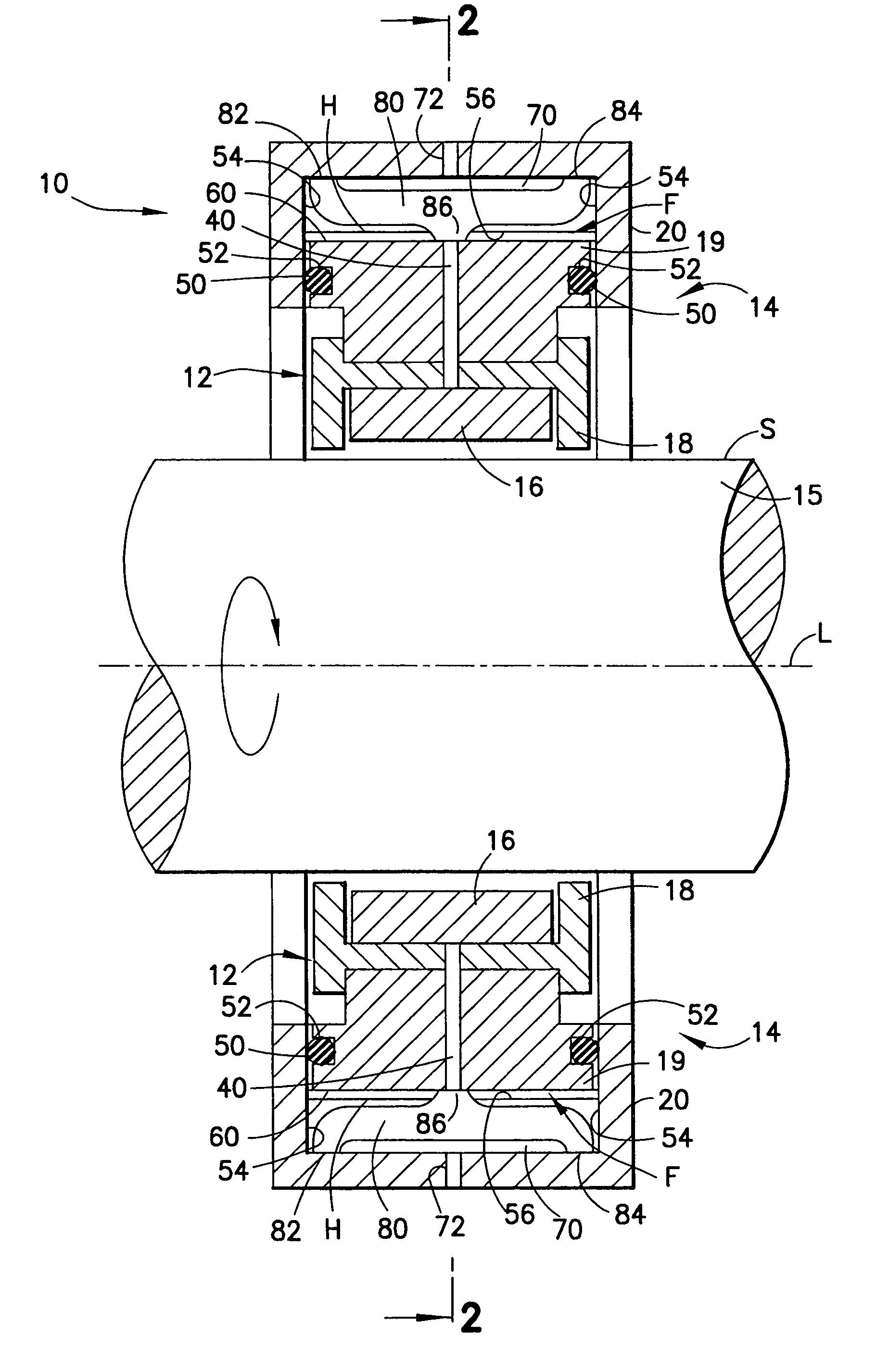
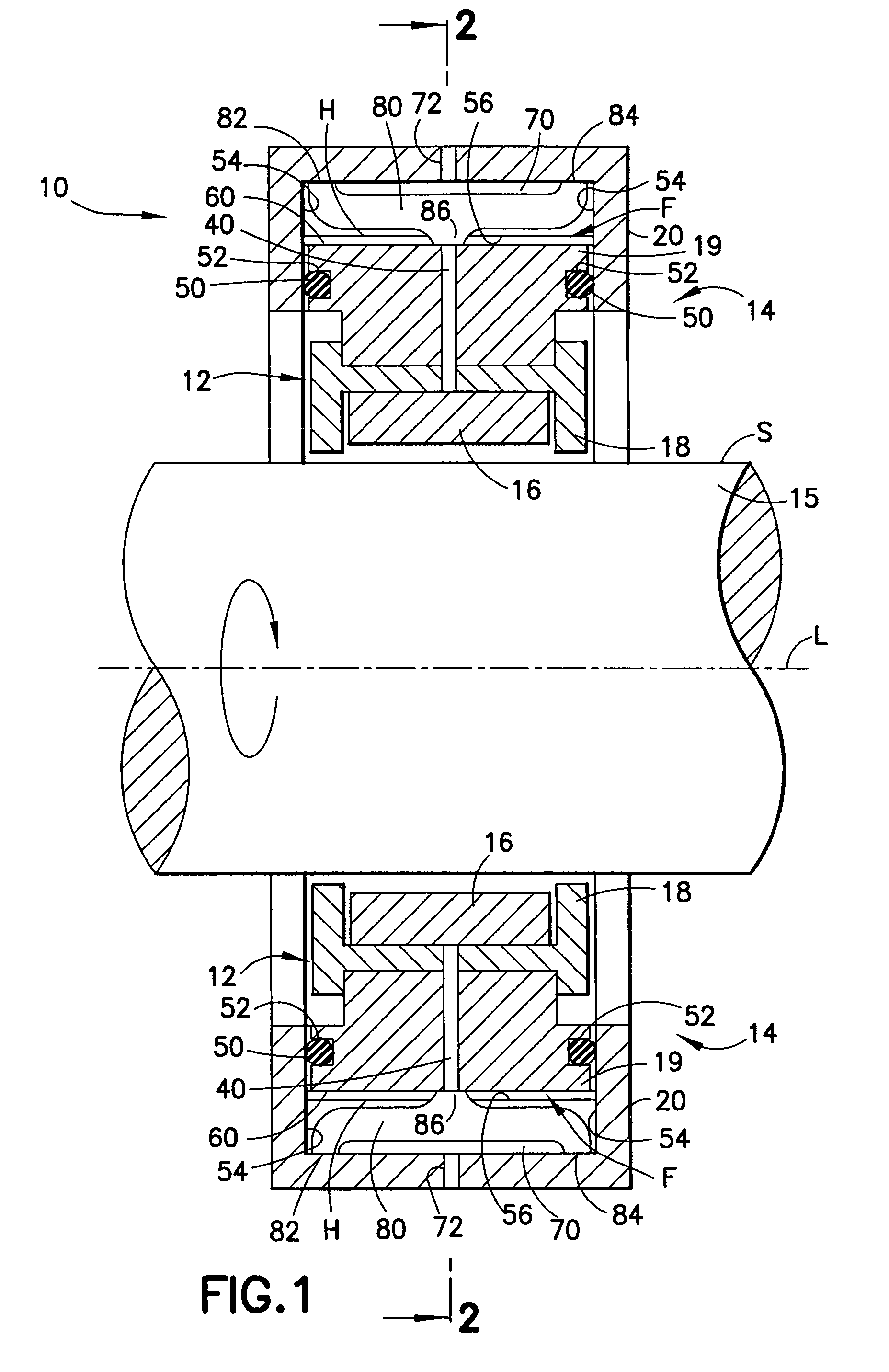
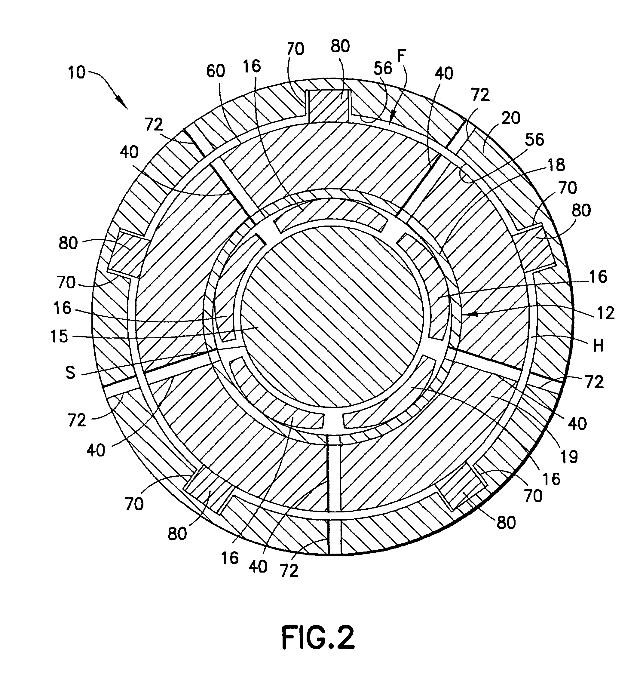
[0042]With continued reference to FIGS. 1 and 2 of the drawings, bearing assembly 10 is illustrated. Bearing assembly 10 generally comprises a bearing 12 and a bearing support structure 14 disposed about and radially supporting bearing 12. Bearing 12 is, in turn, disposed about a rotor shaft 15 aligned on a longitudinal central shaft axis L. As illustrated, the major components of bearing assembly 10, namely bearing 12 and support structure 14, are also symmetrical about axis L and rotor shaft 15. Rotor shaft 15 may be a solid element, as illustrated, or be provided as a cylindrical-shaped structure aligned on and rotatable about axis L. Rotor shaft 15 has an outer surface S that is engaged in bearing 12. Bearing 12 is illustrated as a tilt pad bearing as one possible embodiment of bearing 12. However, bearing 12 may also take the form of a roller bearing, comprising an inner race rigidly attached to rotor shaft 15, an outer race having an outer cylindrical surface and an annular si...

second embodiment

[0064]FIGS. 9A and 9B illustrate bearing assembly 10b with centering elements 150b. In centering elements 150b, intermediate beam member 166a is omitted and distal beam member 164b and base beam member 162b are connected by a central connecting “post” portion or member 168b of body 160b. Post member 168b will permit distal beam member 164b to deflect about post portion 168b and compress towards base beam member 162b when radial force is applied to centering element 150b. Base beam member 162b and distal beam member 164b may each define an elongated internal space 174b making these members relatively thin-walled in the vicinity of post portion 168b to allow for the deflection and compression of distal beam member 164b about post member 162b. One or both of internal spaces 174b may be omitted, if desired, in centering element 150b. Additionally, internal spaces 174b may each be alternatively provided as a plurality of individual internal spaces 174b, for example, in the manner shown i...

third embodiment

[0065]FIGS. 10A and 10B illustrate bearing assembly 10b with centering elements 150c. In centering elements 150c, base beam member 162c, intermediate beam member 166c, and distal beam member 164c define an overall S-shape for centering elements 150c. Intervening spaces 172c are defined between intermediate beam member 166c and base beam member 162c and distal beam member 164c and intermediate beam member 166c to allow deflection of distal beam member 164c and intermediate beam member 166c. Deflection characteristics of distal beam member 164c and intermediate beam member 166c may be controlled by the sizing of cut-out areas 180 in the areas of body 160c connecting intermediate beam member 166c to base beam member 162c and connecting distal beam member 164c to intermediate beam member 166c. Cut-out areas 180 may be provided in shapes other than the circular shape illustrated in FIGS. 10A and 10B, such as oval, elliptical or be simply elongated, generally polygonal shaped cut-out area...


PUM

PropertyMeasurementUnit
circumferenceaaaaaaaaaa
radial forcesaaaaaaaaaa
speedaaaaaaaaaa

Abstract

The bearing assembly includes an annular bearing in which the shaft is disposed and a support structure for supporting the bearing. The bearing support is mounted about and radially supports the bearing. The bearing support at least in part defines a squeeze film annulus of the bearing assembly. A plurality of centering elements is associated with the bearing and bearing support and act to center the bearing within the squeeze film annulus. The centering elements are provided at radially spaced locations around the bearing. The centering elements may also be cylinder springs provided at uniformly spaced locations around the bearing. The centering elements may additionally be load cell springs provided at uniformly spaced locations around the bearing. In an alternative embodiment, a singular annular wave spring may be provided in place of the plurality of centering elements.

Description

BACKGROUND OF THE INVENTION[0001]1. Field of the Invention[0002]The present invention relates to bearings, such as roller bearings, journal bearings, sleeve bearings and the like, used to support rotating shafts in turbomachinery such as compressors and turbines and, more particularly, a bearing assembly including a squeeze film damper with a support structure for centering support of a bearing within the squeeze film damper annulus.[0003]2. Description of Related Art[0004]Large axial and radial forces act on high-speed rotors, such as the shafts of compressors or turbines, and these forces are compensated for by appropriately configured and arranged thrust bearings and journal bearings. In addition, it is also necessary to provide compensation for the radial rotor vibrations if trouble-free operation of such turbomachinery is to be ensured. For this purpose, squeeze film dampers are often employed in turbomachines to reduce the amplitude of the rotor vibrations. Typically, a squeez...

Claims


Application Information

Patent Timeline
Patent Type & Authority Patents(United States)
IPC IPC(8): F16C27/06F16C32/06
CPCF16C17/03F16C27/02F16F15/0237Y10T29/49643Y10T29/4932F16C2360/00
Inventor PETTINATO, BRIAN C.DE CHOUDHURY, PRANABESH
Owner ELLIOTT CO
Why Eureka
Try Eureka