Electric machine

A technology of electric machines and hubs, which is applied in the direction of synchronous generators, electrical components, electromechanical devices, etc., and can solve the problems that liquids and small particles cannot be sealed.

Inactive Publication Date: 2005-03-09
ROBERT BOSCH GMBH
View PDF1 Cites 0 Cited by
  • Summary
  • Abstract
  • Description
  • Claims
  • Application Information

AI Technical Summary

Problems solved by technology

Due to this limited sealing effect, the following disadvantages are caused: the annular gap sealing structure does not have a sealing effect on liquids and smaller particles

Method used


Image

  • Electric machine
  • Electric machine
  • Electric machine

Examples


Embodiment Construction

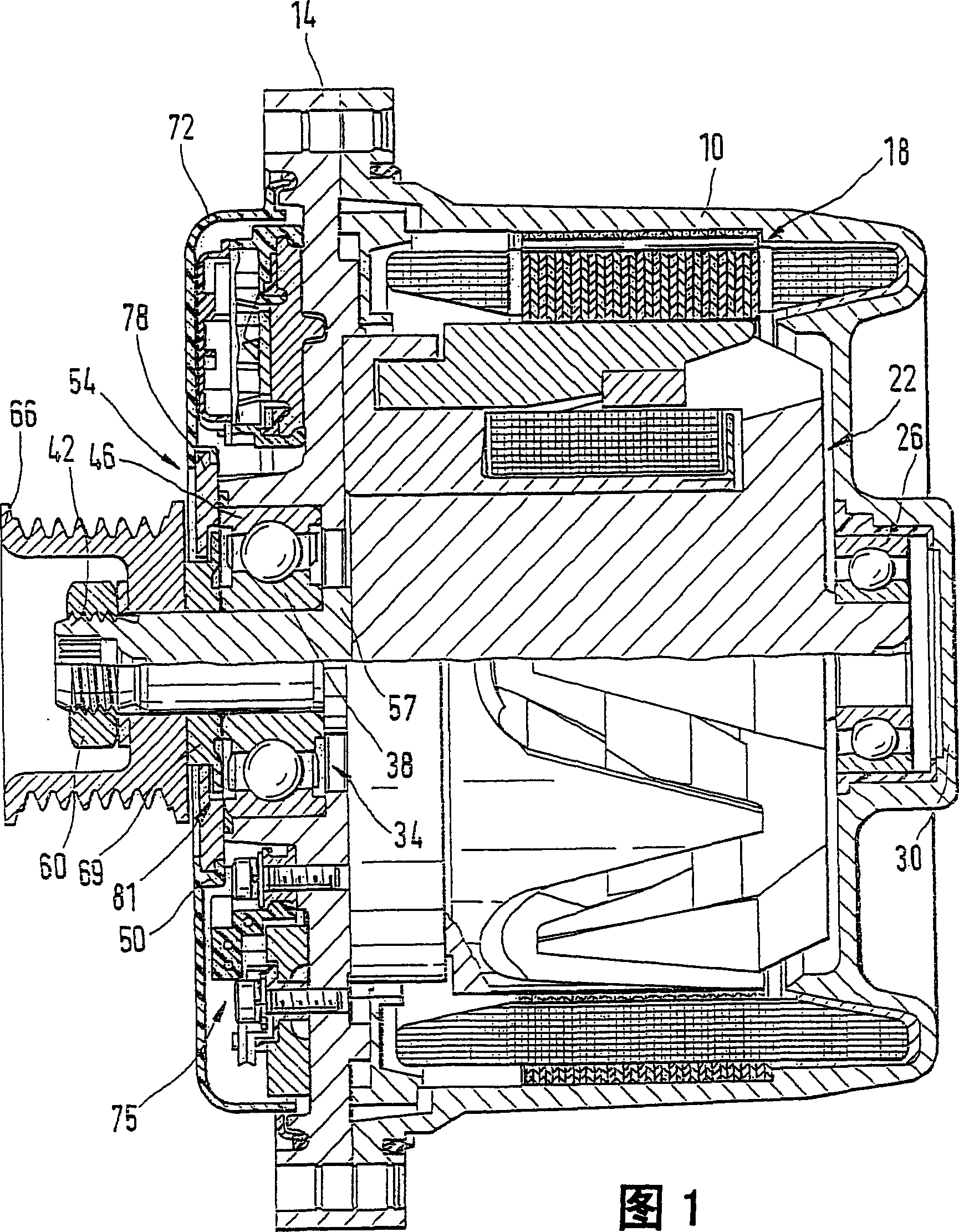
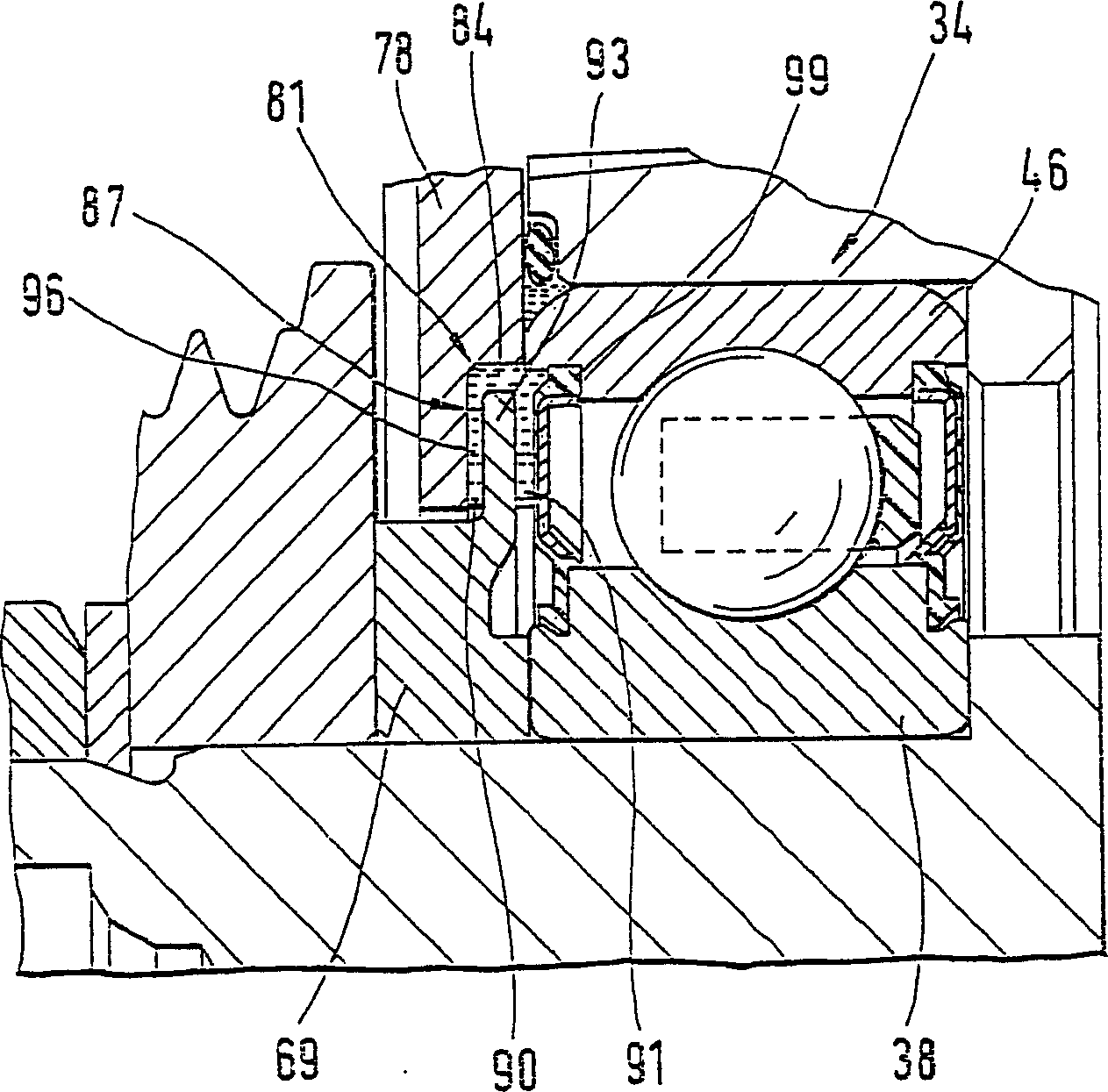
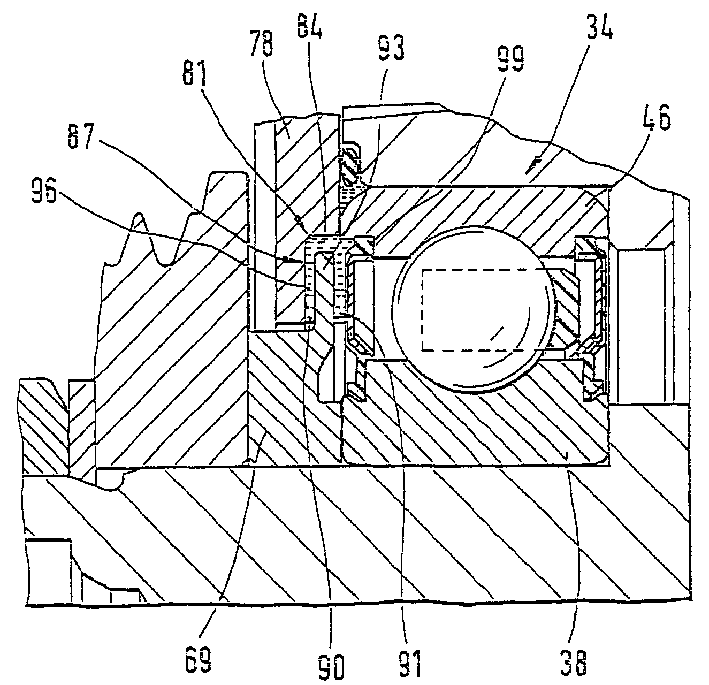
[0011] The upper half of FIG. 1 shows a longitudinal sectional view of the electrical machine according to the invention. The electrical machine, here in the form of a generator, has a pot-shaped housing 10, which is closed by a housing cover 14, in which a stator 18 is fastened, which surrounds the The shape surrounds a rotor 22. The rotor 22 is supported on one side via a bearing 26 on the housing base 30 and on the other side via a roller bearing 34 in the housing cover 14 . In this case, the rolling bearing 34 is supported on a rotor shaft 42 via a shaft-side bearing ring 38 . On the hub side, the roller bearing 34 is supported in the housing cover 14 via a hub-side bearing ring 46 . Here, the housing cover 14 forms a hub 54 with a shoulder 50 . The axial position of the shaft-side bearing ring 38 is limited by a shaft shoulder 57 , and the shaft-side bearing ring 38 passes through a shoulder 63 of a pulley 66 by means of a nut 60 and a second shaft arranged between the...


PUM


Abstract

The invention relates to an electric machine, especially a generator, that is provided with a shaft (42) with a hub (54) and an annular gap (81). The annular gap (81) is formed between the shaft (42) or at least one first component (69) which is rotationally fixed to the shaft (42) and the hub (54) or at least one second component (78) which is rotationally fixed to the hub (54). The annular gap (81) is at least partially filled with a pasty material (84), especially fat.

Description

technical field [0001] The invention relates to an electrical machine, in particular a generator. Background technique [0002] WO 99 / 17430 discloses a generator with an annular gap seal. A spacer between a pulley and a rolling bearing is arranged in such a way that it forms an annular gap with a component fastened to the hub. However, this annular gap has only a limited sealing effect. The function of the annular gap sealing structure is only to prevent larger particles from entering the space between the spacer and the rolling bearing. This limited sealing action has the disadvantage that the annular gap seal has no sealing action against liquids and smaller particles. Contents of the invention [0003] According to the invention, an electrical machine is proposed, in particular a generator, having a shaft, a hub, and an annular gap formed in the shaft or at least one first non-rotatable connection with the shaft. Between the component and the hub or at least one sec...

Claims


Application Information

Patent Timeline
Patent Type & Authority Patents(China)
IPC IPC(8): F16C33/78H02K5/124H02K5/15H02K5/16H02K5/173H02K19/22H02K19/24
CPCH02K5/124H02K19/24
Inventor 格哈德・普夫吕格尔托马斯・伦格费尔德埃里希・沃尔夫沃尔夫冈・戈特费里德
Owner ROBERT BOSCH GMBH
Why Eureka
Try Eureka