Unlock instant, AI-driven research and patent intelligence for your innovation.

Optical disk device

A technology of optical discs and equipment, applied in the field of optical disc equipment, can solve problems such as damage to optical discs, interference of driving voltage, short focal length of bifocal lenses, etc.

Inactive Publication Date: 2005-03-16
SONY CORP
View PDF0 Cites 0 Cited by
  • Summary
  • Abstract
  • Description
  • Claims
  • Application Information

AI Technical Summary

Problems solved by technology

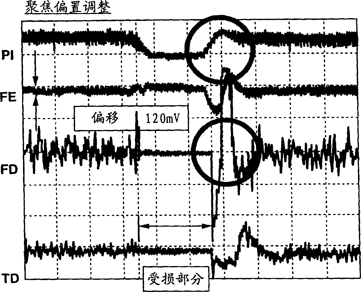
Also, after passing through the damaged part, the offset voltage is applied to the error signal again, so that the servo mechanism system follows the error, so the driving voltage is disturbed
Due to the disturbance of the drive voltage, the signal reproduced from the optical disc is affected and its waveform is disturbed, making the error rate worse
[0009] The second problem occurs when there is a difference in the degree of damage at the position of the disc when the defocus adjustment and off-track adjustment are performed automatically and at the position of the disc when the disc is reproduced
then the disc will be damaged
In addition, since the focal length of the bifocal lens is short due to the characteristics of the lens, it is difficult to provide a mechanical stopper in the design to prevent collision between the disc and the objective lens in consideration of surface blurring during disc rotation

Method used


Image

  • Optical disk device
  • Optical disk device
  • Optical disk device

Examples


Embodiment Construction

[0032] Embodiments to which the present invention is applied are explained below with reference to the drawings.

[0033] An optical disc apparatus as a first embodiment to which the present invention is applied includes an objective lens (hereinafter referred to as a bifocal lens) having focal points at two positions in the optical axis direction. figure 2 shows an optical disc device according to an embodiment to which the present invention is applied.

[0034] The optical disc device 1 includes an optical disc 2, a spindle motor 3, an optical pickup 4, an RF amplifier 5, a disc discrimination section 6, a jitter measurement section 7, an error signal generation section 8, an error center measurement section 9 and a data processing section 10, a focus control section 11. A focus servo mechanism 12, a tracking control section 13, and a tracking servo mechanism 14.

[0035] The optical disc 2 may be any of various disc formats such as CD (Compact Disc), DVD (Digital Versatil...


PUM

PropertyMeasurementUnit
thicknessaaaaaaaaaa
thicknessaaaaaaaaaa
reflectanceaaaaaaaaaa

Abstract

Deterioration of an error rate due to disturbance of a reproduced signal is prevented by carrying out focus balance adjustment and tracking balance adjustment, with use of a focus control section for causing a focus servo to control the focus balance, based on a jitter value measured by a jitter measurement section, and a balance-adjusted TE signal generated by an error signal generating section, and a tracking control section for causing a tracking servo to control the tracking balance, based on an error center value measured by an error center measurement section and a balance-adjusted signal generated by an error signal generating section. Also, the focus servo carries out focus down-search thereby to switch on correctly the focus.

Description

technical field [0001] The invention relates to an optical disc device for balancing focus error signals and tracking error signals to perform defocus adjustment and off-track adjustment. [0002] The present invention also relates to an optical disc device for focusing a light beam radiated from an optical pickup onto a signal recording surface of the optical disc or the like using a return signal from the optical disc or the like. Background technique [0003] Recently, an objective lens having focal points at two positions in the optical axis direction (hereinafter referred to as a bifocal lens) is used to reproduce CD (Compact Disk), DVD (Digital Versatile Disk) by one optical disk reproducing apparatus. [0004] Generally, in an optical disk reproducing apparatus, defocus and off-track adjustments are automatically performed when the apparatus is started. Defocus adjustment is performed so that the light beam from the optical pickup is focused on the signal recording s...

Claims


Application Information

Patent Timeline
Patent Type & Authority Patents(China)
IPC IPC(8): G11B7/00G11B7/09
CPCG11B7/0948G11B2007/0013G11B2007/0006G11B7/094G11B7/0945G11B7/08511
Inventor 铃木健一
Owner SONY CORP