
Small electric motor

A kind of electric motor and small technology, which is applied in the direction of manufacturing motor generators, electric components, electrical components, etc., and can solve the problems of narrow space, restrictions, and large radial direction for disposing the gear train part 215

Inactive Publication Date: 2005-04-06
SANKYO SEIKI MFG CO LTD
View PDF0 Cites 0 Cited by
  • Summary
  • Abstract
  • Description
  • Claims
  • Application Information

AI Technical Summary

Problems solved by technology

However, as the cage member 206, a certain thickness is also required, and the overall radial direction tends to become larger.
In addition, since the circuit board 207 and the holder member 206 are structured to enter the gear train portion 215 of the small motor 201, the space for arranging the gear train portion 215 becomes narrow, and it is easy to limit the gears and the like to make small structures.

Method used


Image

  • Small electric motor
  • Small electric motor
  • Small electric motor

Examples


Embodiment Construction

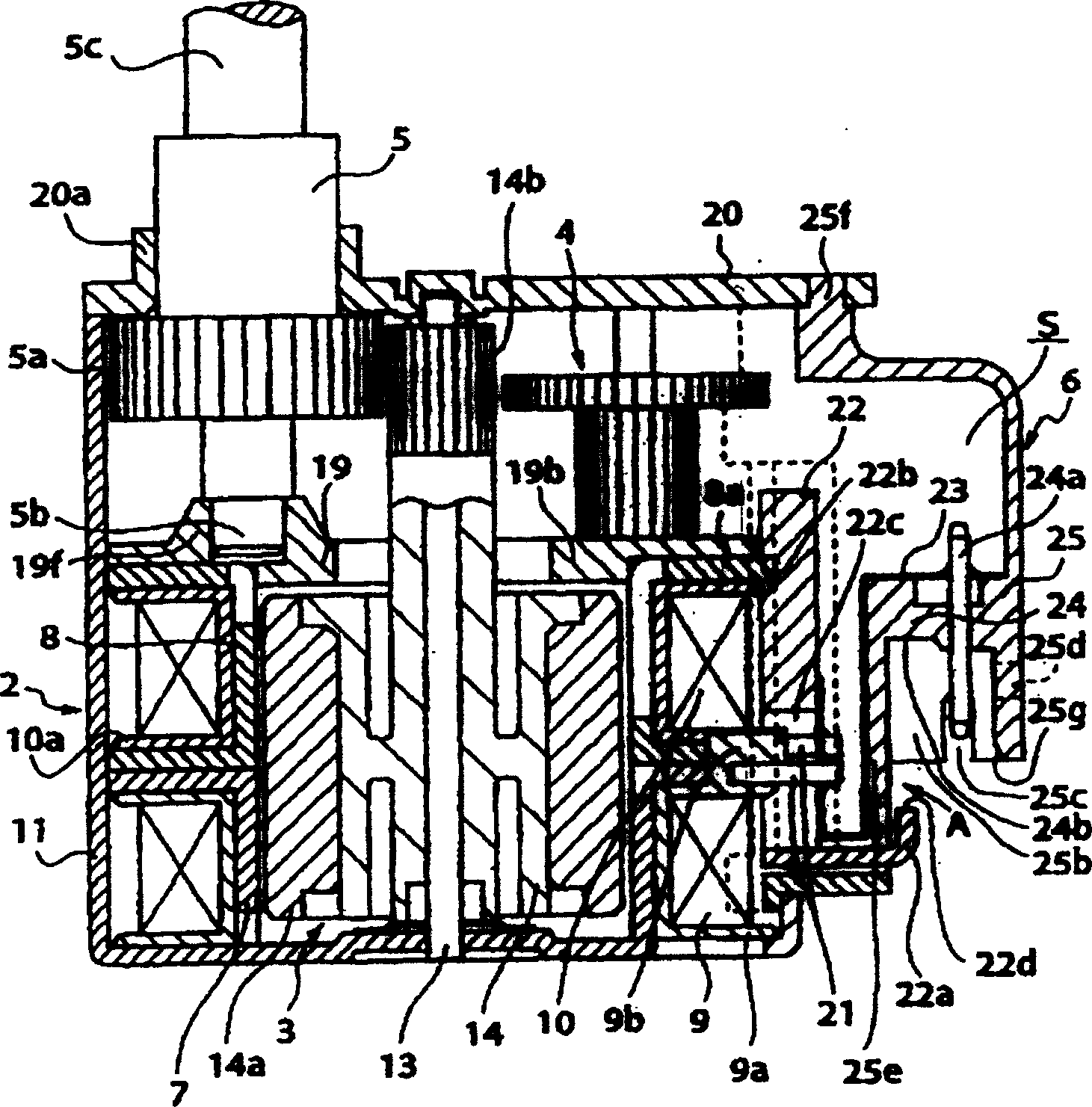
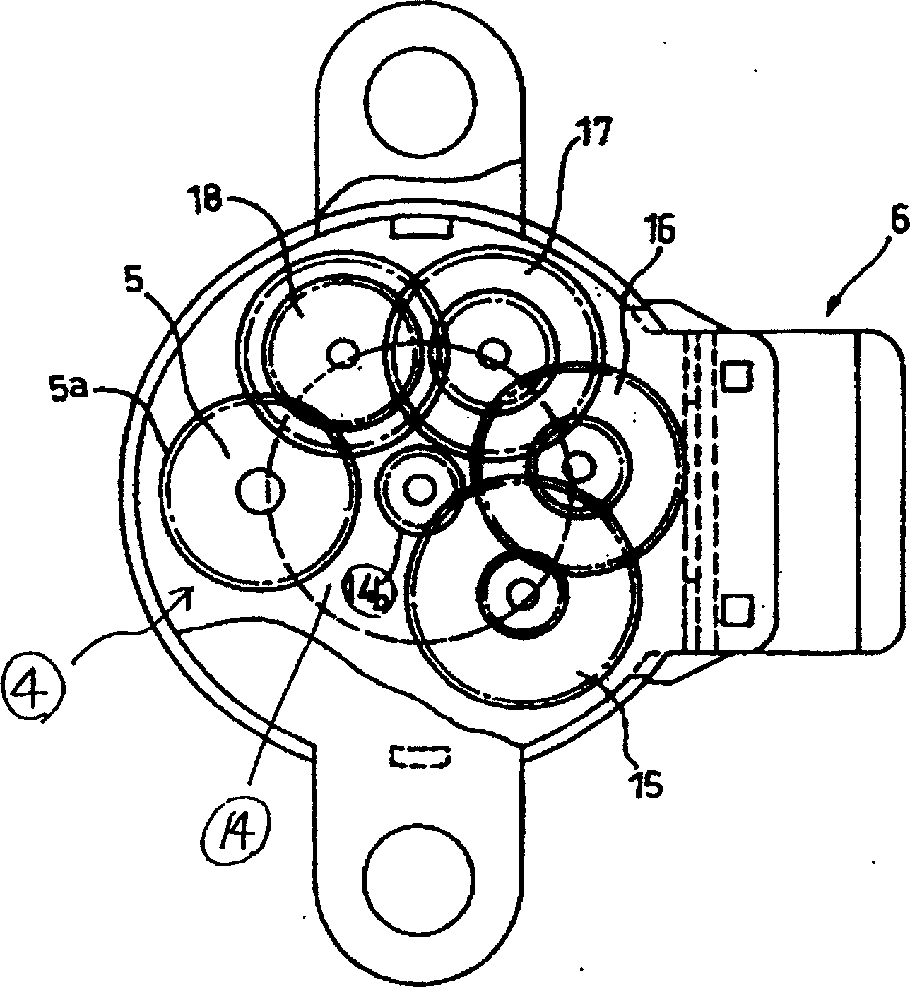
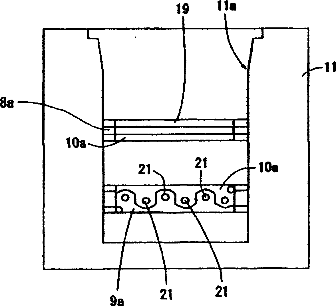
[0031] Combine now Figure 1 to Figure 10 Embodiments of the present invention will be described. combine first Figure 1 to Figure 8 The small motor of the first embodiment will be described.

[0032] First, use figure 1 and Figure 4 to Figure 7 The structure of the terminal part and the support base which are the key points of the present invention will be described. The connecting member 6 of the terminal portion is a connecting portion 24 to be connected to a connector inserted from the outside, and a cover portion 25 having an opening 25b that serves as an accommodating space for the connector inserted from the outside, and is integrated by fixing or synthetic resin. Formed into a structure that integrates the two.

[0033] The connecting portion 24 is provided integrally with the cover portion 25 at the center of the cover portion 25 described later, and holds the connector pins 24a and the flexible substrate 23 constituting the conduction path.

[0034] cover pa...


PUM


Abstract

The present invention relates to a compact motor. A cutout part is formed at one part of a motor case, and a connector part where an external connector for energizing a motor coil is interlocked to the cutout part is provided, a connector part where the external connector being inserted from the outside is interlocked is stuck to or is integrated with a cover part that has an opening part that becomes space for receiving the external connector by synthetic resin, and a flexible substrate is interposed between the motor coil and the connector as a conductive member. Said compact motor reduces the number of parts for composing a terminal part, can simplify the mounting structure of a circuit board part, at the same time, can be miniaturized, and can increase the space of a train wheel part.

Description

technical field [0001] The present invention relates to a small electric motor in which a connector is fitted into a connector housing to perform electrical connection. Background technique [0002] in the past we knew Figure 11 Shown Japanese Patent Publication No. 1998 No. 14170 discloses a small electric motor. The terminal part 202 suitable for supplying current to the winding of the small motor 201 includes: a terminal pin 205 disposed between the two windings 203, 204; a cage member 206 inserted through the terminal pin 205 and fixed; A circuit board 207 on the component 206; a connector housing 208 electrically connected to the circuit board 207; and a cover 209 covering these components. [0003] The assembly of the terminal portion in the conventional small motor 201 will now be described. First, the circuit board 207 is inserted into the circuit board insertion hole of the holder member 206 so that one side thereof abuts against the holder member 206 . Next, th...

Claims


Application Information

Patent Timeline
Patent Type & Authority Patents(China)
IPC IPC(8): H02K5/22
CPCH02K5/04H02K5/08H02K5/22H02K15/14
Inventor 永井敦北泽富男和田隆平
Owner SANKYO SEIKI MFG CO LTD
Features
  • Generate Ideas
  • Intellectual Property
  • Life Sciences
  • Materials
  • Tech Scout
  • Unparalleled Data Quality
  • Higher Quality Content
  • 60% Fewer Hallucinations
Learn More