Supercharge Your Innovation With Domain-Expert AI Agents!

Oscillating motor and motor control equipment and method

一种振动电动机、电动机的技术,应用在交流电动机控制、用于单相电流的同步电动机、电动组件等方向,能够解决费用增加、不能做高速往复旋转运动、不能被应用等问题

Inactive Publication Date: 2005-06-08
LG ELECTRONICS INC
View PDF0 Cites 0 Cited by
  • Summary
  • Abstract
  • Description
  • Claims
  • Application Information

AI Technical Summary

Problems solved by technology

[0029] However, as mentioned above, although the motor can rotate forward or backward at high speed, it cannot do high-speed reciprocating rotation in a certain area
In this way, it cannot be applied to machinery or equipment that requires high-speed reciprocating rotation
In addition, if it is adopted, a conversion mechanism for converting rotary motion into linear motion must be additionally installed, which leads to a problem of cost increase

Method used


Image

  • Oscillating motor and motor control equipment and method
  • Oscillating motor and motor control equipment and method
  • Oscillating motor and motor control equipment and method

Examples


Embodiment Construction

[0051] Reference will now be made to the preferred embodiments of the invention, examples of which are illustrated in the accompanying drawings.

[0052] Figure 4 is a perspective view showing a vibration motor according to a preferred embodiment of the present invention, Figure 5 is a vertical sectional view of a vibration motor according to a preferred embodiment of the present invention, Image 6 is according to a preferred embodiment of the present invention along Figure 5 Sectional view taken along line 'f-f' of

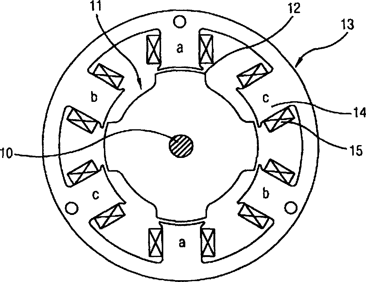
[0053] As shown in the drawing, a stator 410 is provided, a rotor 440 is rotatable inside the stator 410, and a rotation shaft 470 is at the center of the rotor as an extraction shaft.

[0054] The stator 410 is provided with a stator core 420 stacked by laminations. A pair of stator teeth on which a coil is wound is formed in the reciprocating rotation areas 400 and 400 - 1 in front and rear of the inner circumferential surface of the stator core 420 exc...


PUM


Abstract

A vibration motor includes: a first tooth having recesses and protrusions on its front surface; a stator having first teeth formed in pairs on the surface of its inner circumference; a rotor having a front surface of its second teeth having recesses and protrusions, and engages the recesses and protrusions on the first tooth of the stator. The motor can rotate reciprocally in the rotating area without any conversion device to convert it into linear motion. Plus, it can be easily connected to existing equipment.

Description

technical field [0001] The present invention relates to a vibration motor, and more particularly to a vibration motor whose concavities and convexities are arranged on the inner circumferential surfaces of a rotor and a stator to increase the contact area, thereby increasing the torque of the motor, and controlling the AC power applied to the motor , to variably control the area where the rotor reciprocates, thereby increasing the efficiency of the compressor. Background technique [0002] Generally, an electric motor controls the operation of a switching device to turn on or off power to a coil wound on a polyphase stator to generate a rotational torque. Because the excitation state of the rotor and stator of the motor changes continuously, a forward rotational moment is formed through the generated magnetic attraction force. If the excitation state between the rotor and the stator of the motor does not change, the rotor will stop at a specific Location. [0003] In addit...

Claims


Application Information

Patent Timeline
Patent Type & Authority Patents(China)
IPC IPC(8): H02K1/14H02K1/24H02K1/28H02K19/10H02K33/12H02P25/02H02P25/08
CPCH02K1/146H02K1/246H02K19/103H02K33/12H02P25/032
Inventor 林俊荣郑润撤
Owner LG ELECTRONICS INC
Features
  • R&D
  • Intellectual Property
  • Life Sciences
  • Materials
  • Tech Scout
  • Unparalleled Data Quality
  • Higher Quality Content
  • 60% Fewer Hallucinations
Learn More