Supercharge Your Innovation With Domain-Expert AI Agents!

Hydraulic brake controlling device for vehicle

A control device, a vehicle braking technology, applied in the direction of brake transmission, bicycle brakes, brakes, etc., can solve the problems of increased power consumption, chaotic hydraulic control of wheel brakes, reduced service life, etc. The effect of power reduction

Inactive Publication Date: 2005-07-20
HONDA MOTOR CO LTD
View PDF1 Cites 0 Cited by
  • Summary
  • Abstract
  • Description
  • Claims
  • Application Information

AI Technical Summary

Problems solved by technology

That is, in the state where only a part of the plurality of brake operating members is operated, if the brake hydraulic pressure of the wheel brake is controlled by using anti-lock brake control, etc., when the other brake operating members are operated again, the brake hydraulic pressure is controlled against the brake operating member. affected and hindered the operation of the new brake operator
However, when a new brake operator is operated, the hydraulic control of the wheel brakes becomes confused due to the additional input to the currently hydraulically controlled wheel brakes.
Moreover, it also causes an increase in power consumption and a reduction in the service life of the control valve mechanism that operates until it does not need to be operated.

Method used


Image

  • Hydraulic brake controlling device for vehicle
  • Hydraulic brake controlling device for vehicle

Examples


Embodiment Construction

[0011] Hereinafter, an embodiment of the present invention will be described based on an embodiment of the present invention shown in the drawings.

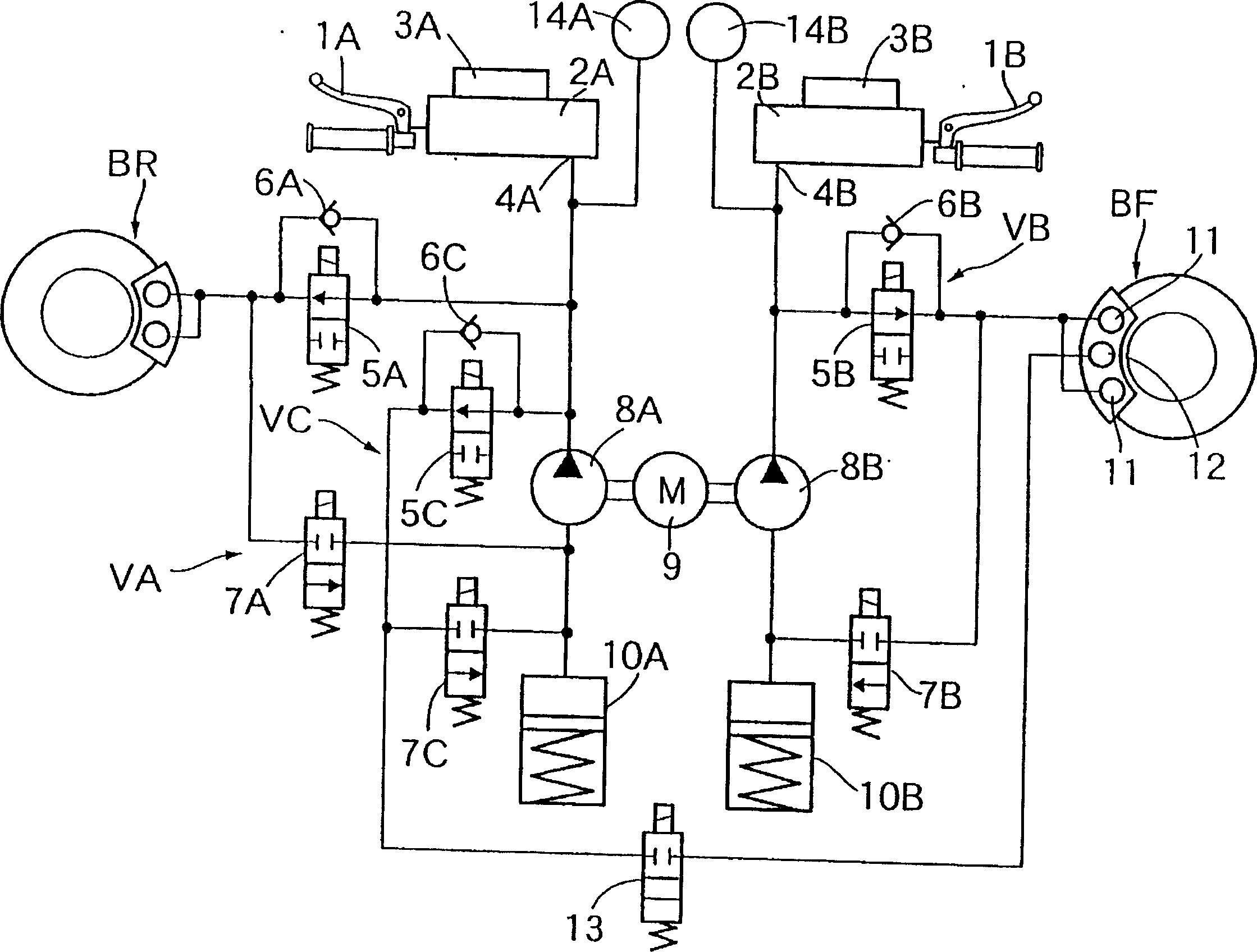
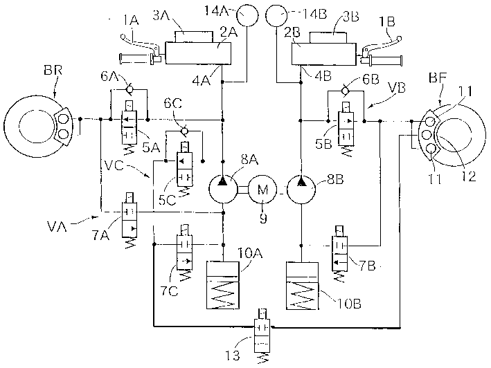
[0012] Fig. 1 is a hydraulic circuit diagram of a braking device of a motorcycle. In response to the cyclist who is a motorcycle driver operating the brake lever 1A as a brake operating member with his left hand, the hydraulic pressure is output from the outlet 4A of the main hydraulic cylinder 2A of the attached container 3A, and in response to the cyclist using his right hand. When the brake lever 1B serving as a brake operating member is operated for braking, the hydraulic pressure is output from the outlet 4B of the master cylinder 2B of the attached tank 3B.

[0013] The outlet 4A of the main hydraulic cylinder 2A is connected with the rear wheel brake BR through the normally open solenoid valve 5A, and the check valve 6A that allows the brake fluid to flow from the rear wheel brake BR to the main hydraulic cylinder 2A is co...


PUM


Abstract

In a brake hydraulic pressure control device for a vehicle in which a plurality of master cylinders outputting hydraulic pressures to the brake operating members as the vehicle driver operates the brake operating members are connected with a single wheel brake, the present invention aims to avoid an increase in power consumption and enhance the durability of control valve means by solving a problem that occurs when the operation of each of a plurality of brake operating members is carried out in steps while the accuracy of controlling brake hydraulic pressure is enhanced. Control valve means VC and VB capable of independently controlling the brake hydraulic pressures applied to the wheel brake BF are provided between the plurality of master cylinders 2A and 2B and the wheel brake BF, and are actuated for controlling the hydraulic pressures only when detection means 14A and 14B detect the operation of the brake operating members 1A and 1B corresponding to the control valve means VC and VB.

Description

technical field [0001] The present invention relates to a vehicle brake hydraulic pressure control device that connects a plurality of master hydraulic cylinders that output hydraulic pressure in response to a driver's operation of a plurality of independently operable brake operating members to a single wheel brake. Background technique [0002] Conventionally, such a brake fluid pressure control device has been disclosed in, for example, Japanese Patent Application Laid-Open No. 4-368267 or the like. [0003] Such a brake hydraulic device is, for example, such that even if any one of a plurality of brake operating members is operated, the wheel brakes mounted on the front wheels can be braked. , in order to carry out finer control, it is best to set up a control valve mechanism that can independently control the hydraulic pressure between each main hydraulic cylinder and the common wheel brake. [0004] However, when controlling the brake hydraulic pressure of the wheel b...

Claims


Application Information

Patent Timeline
Patent Type & Authority Patents(China)
IPC IPC(8): B60T8/26B60T8/00B60T8/32B60T8/34B60T8/48B60T13/12B60T13/68B62L1/00B62L3/02B62L3/08
CPCB60T8/3225B60T13/686B62L1/00B62L3/08
Inventor 若林威谷一彦
Owner HONDA MOTOR CO LTD
Features
  • R&D
  • Intellectual Property
  • Life Sciences
  • Materials
  • Tech Scout
  • Unparalleled Data Quality
  • Higher Quality Content
  • 60% Fewer Hallucinations
Learn More