Structure for preventing centrifugal compressor from reverse rotation

A compressor, centrifugal technology, applied in mechanical equipment, machine/engine, pump control, etc., can solve the problem of component damage, reduce the first radial bearing 9A and the second radial bearing 9B, large noise, etc., to achieve The effect of improving overall longevity and reliability

Inactive Publication Date: 2005-08-03
LG ELECTRONICS (TIANJIN) APPLIANCES CO LTD
View PDF0 Cites 0 Cited by
  • Summary
  • Abstract
  • Description
  • Claims
  • Application Information

AI Technical Summary

Problems solved by technology

[0008] However, the compressor with the above structure has the following problems: First, during the normal compression process in which the compressor compresses the medium in the low-temperature and low-pressure state through the suction port SP to form a high-temperature and high-pressure state, a power failure or abnormal drive of the compressor occurs When the power supply is cut off to make the compressor suddenly stop driving, in order to balance the pressure between the discharge port DP side of the high-pressure part and the suction port SP side of the low-pressure part in the compressor, the flow medium channel 12 through the compressor will flow from The phenomenon of rapid countercurrent flow of the medium from the discharge port DP to the suction port SP. In the above process, through the pressure difference between the suction port SP and the discharge port DP and the rapid countercurrent flow of the medium, the primary compressor fixed at both ends of the rotating shaft 7 The impeller 8A and the secondary compression impeller 8B are momentarily subjected to reverse torque, and the rotating shaft 7 is also rotating in the reverse direction. At this time, the primary compression impeller 8A, the secondary compression impeller 8B and the rotating shaft 7 are reversely rotating, which not only reduces the normal rotation of the rotating shaft 7 The performance of the first radial bearing 9A and the second radial bearing 9B that stably supports the dynamic pressure air of the axial flow self-gravity during rotation, and the components constituting the first radial bearing 9A and the second radial bearing 9B are also the same damaged
Secondly, if a power failure occurs or the power supply is cut off due to abnormal driving, the compressor will suddenly stop driving, and the medium that flows back sharply from the high-pressure discharge port DP to the low-pressure suction port SP will make abnormally loud noises and shorten the overall life of the compressor.

Method used


Image

  • Structure for preventing centrifugal compressor from reverse rotation
  • Structure for preventing centrifugal compressor from reverse rotation
  • Structure for preventing centrifugal compressor from reverse rotation

Examples


Embodiment Construction

[0017] The structure for preventing reverse rotation of the centrifugal compressor of the present invention will be further described in detail in conjunction with the accompanying drawings and specific embodiments:

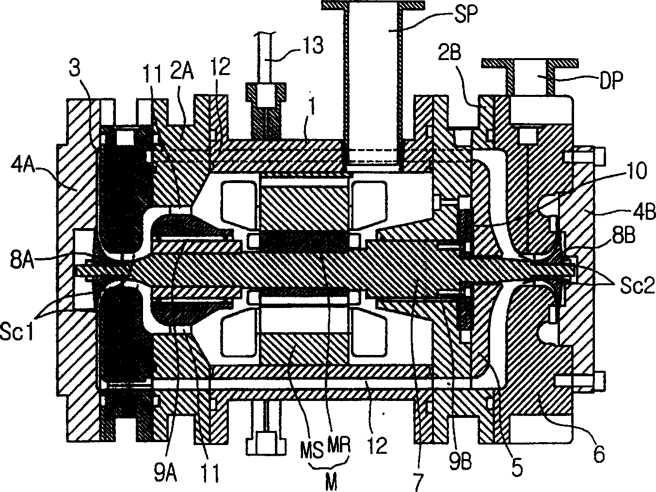
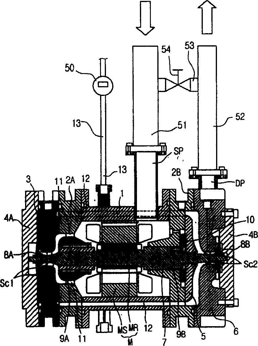
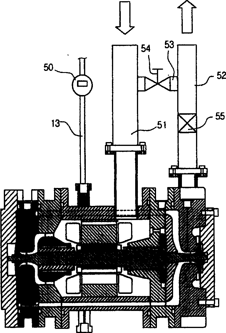
[0018] Such as figure 2 As shown, for the low-temperature and low-pressure medium that flows in through the suction port SP, it is compressed to a high-temperature and high-pressure state by the secondary compression and compression action of the primary compression impeller 8A and the secondary compression impeller 8B, and then discharged through the discharge port DP. , the structure of the compression part is the same as that of the prior art, the difference is that the suction pipe 51 is connected on the suction port SP of the compressor, the discharge pipe 52 is connected on the discharge port DP of the compressor, and the flow pipe with the diverter valve 54 is installed 53 is arranged between the suction pipe 51 and the discharge pipe 52, so that they com...


PUM


Abstract

The present invention provides the structure for preventing centrifugal compressor from reverse rotation. The structure includes suction pipe connected to the suction port of the compressor, exhaust pipe connected to the exhaust port of the compressor, flow path pipe with shunt valve connected between the suction pipe and the exhaust pipe for mutual communication, and power off sensor set in the power cord. The shunt valve is made to open or shut via controlling the power off sensor and the high temperature and high pressure medium is made to flow from the exhaust port to the suction port for pressure balance between them. In case that the power supply is turned off and the compressor stops suddenly owing to power-off or abnormal compressor, the present invention can prevent the reverse rotation of the rotating shaft, abnormal flow of the medium gas inside the compressor, abnormal noise and corresponding effect on the compressor parts.

Description

technical field [0001] The invention relates to a centrifugal compressor, in particular to a structure for preventing reverse rotation of the centrifugal compressor. Background technique [0002] In general, compressors can use mechanical operation to compress fluid. Compressors are roughly divided into reciprocating type, scroll type, centrifugal type (axial flow type) and vane type (rotary type). Among them, the centrifugal compressor (also called axial flow compressor) uses the rotational force of the impeller to suck the fluid in the axial direction, and then discharge it in the centrifugal direction for compression. According to the number of impellers and compression chambers, it is divided into primary compression type and The secondary compression type, according to the arrangement of the impellers, is divided into back-to-back type and face-to-face type. [0003] Such as figure 1 As shown, the face-to-face secondary compression centrifugal compressor includes a mo...

Claims


Application Information

Patent Timeline
Patent Type & Authority Patents(China)
IPC IPC(8): F04D27/00
Inventor 崔文畅徐光河金永宽智裕喆王大星
Owner LG ELECTRONICS (TIANJIN) APPLIANCES CO LTD
Why Eureka
Try Eureka