Intelligent oscillating blowing system for drying chamber

An air supply system and fan technology, applied in the direction of dryers, drying, lighting and heating equipment, etc., to achieve the effects of uniform air supply, shortened drying cycle, and small investment

Inactive Publication Date: 2005-09-14
SHANGHAI UNIV OF ENG SCI
View PDF0 Cites 0 Cited by
  • Summary
  • Abstract
  • Description
  • Claims
  • Application Information

AI Technical Summary

Problems solved by technology

[0003] The purpose of the present invention is to overcome the disadvantages of the current circular air supply system in the wood drying room, which only rely on the forward and reverse rotation of the fan impeller to supply air, and to provide a system that can automatically and synchronously rotate the bodies of multiple fans in the drying room. Drying room fan rotary air supply system for air supply

Method used


Image

  • Intelligent oscillating blowing system for drying chamber
  • Intelligent oscillating blowing system for drying chamber
  • Intelligent oscillating blowing system for drying chamber

Examples


Embodiment 1

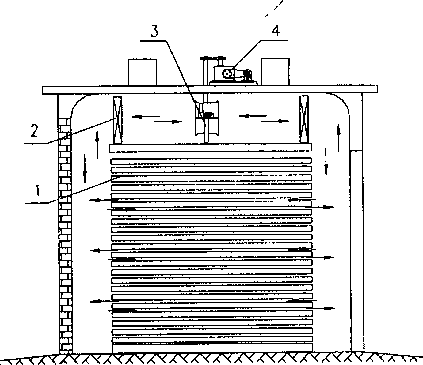
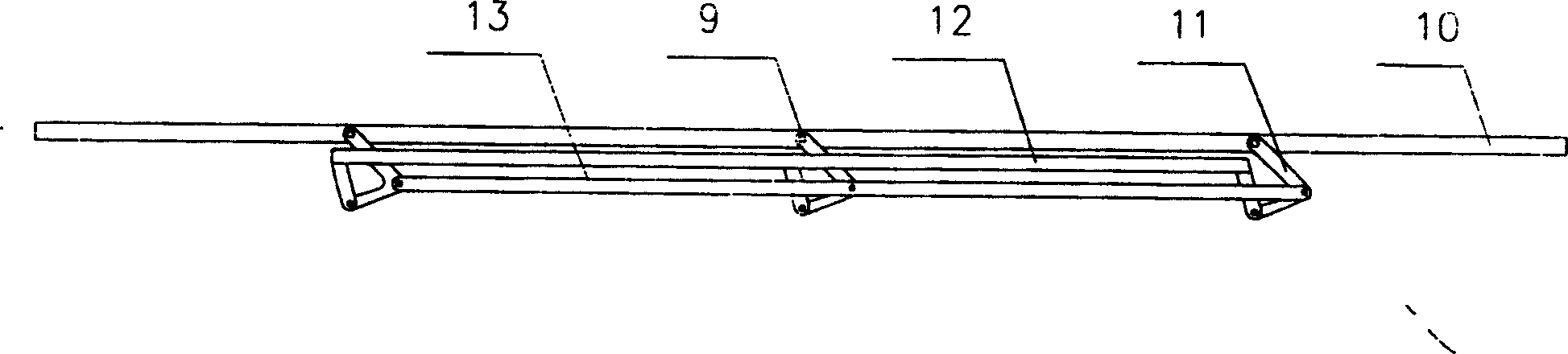
[0018] Depend on image 3 As shown, the link transmission device as a synchronous rotary linkage mechanism is composed of a rocker arm 11 fixed on the shaft of each fan itself, and an active link 13 and an auxiliary link 12 connected to each rocker arm. The connecting rod device ensures that multiple fans rotate synchronously. 10 is a frame among the figure, and 9 is the self rotating shaft of blower fan, and present embodiment uses 3 circulating blowers, as Figure 5 As shown in , choose the self-rotating shaft of the fan on the far right to connect with the driving device.

Embodiment 2

[0020] Such as Figure 4 Shown is a rack and pinion drive that can also be used as a synchronous rotary linkage. The transmission device is composed of a gear 15 fixedly installed on the shaft of each fan itself, and a long rack formed by a short rack 14 meshing with each gear. The long rack is formed between the short racks as required. Steel bars 16 are welded to form. Of course, it can also be directly made into a long rack, but the cost is higher. The rack and pinion device is formed to ensure that multiple fans rotate synchronously, and the self-rotating shaft of the rightmost fan is selected to be connected with the driving device.

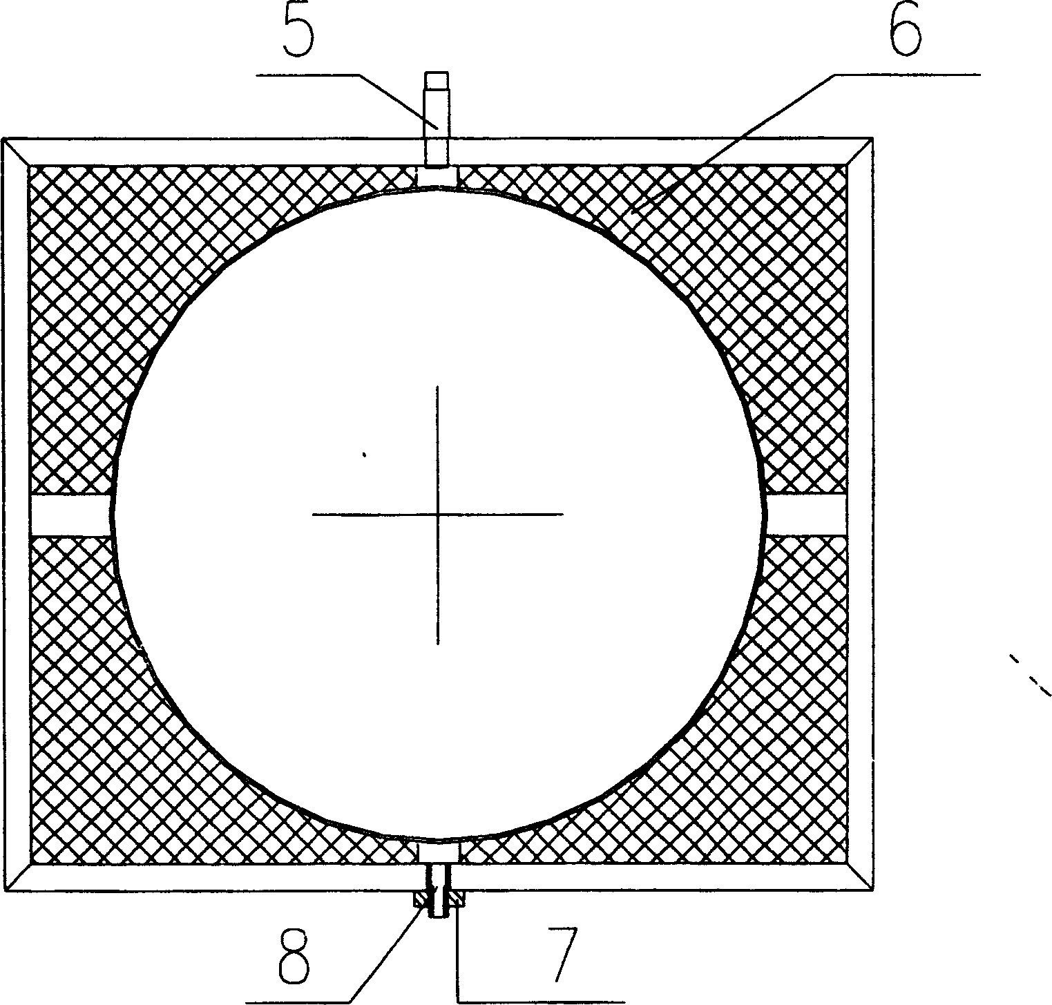
[0021] Fan rotary drives, such as Figure 5 , 6 Shown, it is made up of motor 17, reduction box 18, driving wheel 19, driven wheel 20, drive shaft 21 namely the self-rotating shaft of a blower fan on the right side described in the embodiment, limiter and automatic control device. The fan rotation drive motor drives one of the fans that...


PUM


Abstract

An intelligent blower oscillating system for the baking room to dry wood or medicinal materials is composed of multiple blowers, automatic controller, synchronously oscillating, linkage system connected to the rotary shaft of each blower, and driver connected to the rotary shaft of one blower. Under the drive of said driver, all the blowers can be synchronously oscillating. Its advantages are high drying quality and speed, high efficiency and low cost.

Description

technical field [0001] The invention relates to a fan rotary air supply system used in various drying rooms, drying tunnels and ovens in drying fields such as wood drying and medicine drying. Background technique [0002] Wood drying is the most energy-consuming and indispensable link in the wood processing industry. The drying room is an important equipment for wood drying operations. The hot air circulation system is the key to improving the efficiency of the drying room, saving energy and ensuring product quality. According to different wood drying requirements, there must be an air flow in the drying room with a certain temperature and humidity that can be set and adjusted in real time to flow between the wood surfaces of the wood stack to achieve the purpose of drying the wood. The air flow is driven by the fan. Powered, heated by a heater, flows through the wood stack in a clockwise direction. After a certain period of time, the air flow must flow in the opposite dire...

Claims


Application Information

Patent Timeline
Patent Type & Authority Patents(China)
IPC IPC(8): F26B3/02F26B21/00
Inventor 严平曹伟武钱尚源
Owner SHANGHAI UNIV OF ENG SCI
Why Eureka
Try Eureka