Supercharge Your Innovation With Domain-Expert AI Agents!

Filter device

A filter and filter cartridge technology, applied in the direction of fixed filter elements, filter separation, chemical instruments and methods, etc., can solve the problems of cost increase, troublesome replacement of filter cartridges, etc., to reduce production costs and benefit Ease of assembly and rapid replacement

Inactive Publication Date: 2005-09-21
MAEDA SHELL SERVICES CO LTD
View PDF1 Cites 0 Cited by
  • Summary
  • Abstract
  • Description
  • Claims
  • Application Information

AI Technical Summary

Problems solved by technology

[0005] When assembling the filter cartridge to the mounting seat in the filter device, for those previous filter devices that put the sealing member between the mounting seat, it is necessary to prepare a backup part of the sealing member, so there is Problems that raise costs
In addition, because when replacing the filter cartridge, there is a problem that the sealing member installed between the above-mentioned mounting seat and the filter cartridge deviates from the specified position that exerts the sealing effect, it is necessary to confirm that the sealing member is installed between the mounting seat and the filter cartridge. After the specified position between the filter cartridges, the assembly of the filter cartridge is performed, so the replacement of the filter cartridge is troublesome.

Method used


Image

  • Filter device
  • Filter device
  • Filter device

Examples


Embodiment Construction

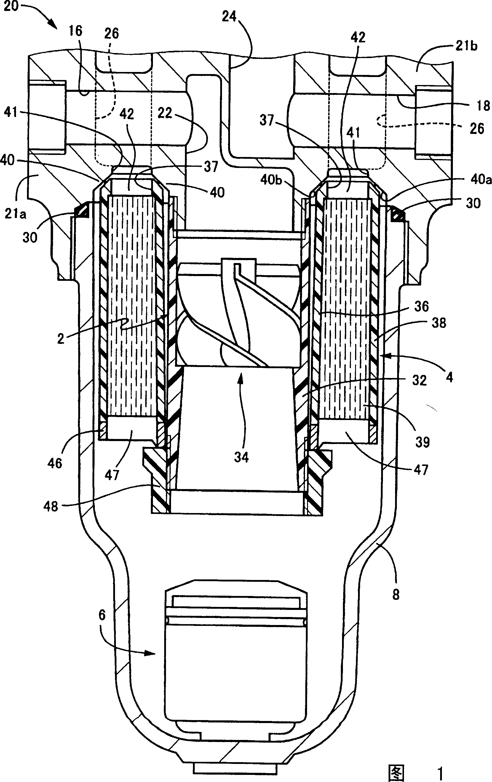
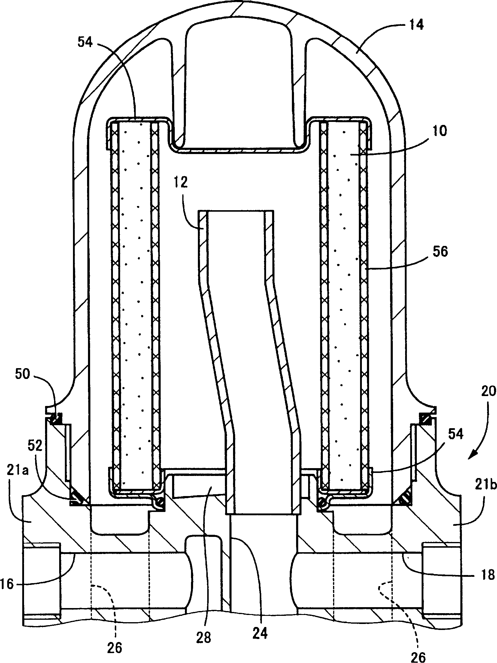
[0022] In order to clarify the present invention more specifically, the specific structure of the filter device of the present invention will be described in detail below with reference to the accompanying drawings.

[0023] Figure 1 and figure 2 A specific example of introducing the structure of the present invention into the filter device for compressed air shown in Japanese Patent Application Laid-Open No. Hei 5-317630, Fig. 1 and figure 2 locally represent its lower and upper halves, respectively. Moreover, in these figures, this filter device consists of a lower housing 8 (refer to FIG. 1 ), an upper housing 14 (refer to figure 2) and a spacer member 20; the first filter cartridge 2, the second filter cartridge 4 and the discharge device 6 are accommodated in the lower housing 8, and the mist filter 10 and collector are accommodated in the upper housing 14. The air cylinder 12 and the above-mentioned spacer member 20 are arranged in the middle position between the lower...


PUM


Abstract

A filter has the filter drum installed to its holder on fluid channel by pushing it. It has good sealing between filter drum and said holder without sealing member. The filter drum can be exchanged easily. The installation holder on the spacing member is composed of the inclined surfaces. The second filter drum is composed of the internal and external drums made of resin, which have the relative inclined surface in contact with that of said installation holder. Its inclined surface has the continuous convex rib along its circumference for good sealing.

Description

technical field [0001] The present invention relates to a filter device, in particular to an improved structure of a filter device which can ensure good sealing between a filter cartridge and its mounting seat in the filter device without having to provide a separate sealing member . Background technique [0002] Conventionally, when a fluid such as gas is used in various factories, various filter devices are installed and applied on the pipeline through which the fluid flows. For example, starting from factory equipment, a filter device for compressed air is installed on the pipeline supplying compressed air to various air compressors used in the medical field and nuclear power plants, and the moisture contained in the supplied compressed air, Remove oil and solid objects to protect the above-mentioned air compressors, or maintain the working quality of these air compressors, and improve their workability. [0003] Moreover, in the various initial filter devices for this ...

Claims


Application Information

Patent Timeline
Patent Type & Authority Patents(China)
IPC IPC(8): B01D29/00B01D29/56
Inventor 前田贞夫
Owner MAEDA SHELL SERVICES CO LTD
Features
  • R&D
  • Intellectual Property
  • Life Sciences
  • Materials
  • Tech Scout
  • Unparalleled Data Quality
  • Higher Quality Content
  • 60% Fewer Hallucinations
Learn More