Automatic tracking device and method

An automatic tracking device and clock signal technology, applied in automatic power control, television, instruments, etc., can solve the problems of reduced tracking quality, impracticality, time-consuming, etc., and achieve the effect of excellent tracking quality, easy implementation, and small memory

Inactive Publication Date: 2005-10-05
MAGIC PIXEL
View PDF0 Cites 0 Cited by
  • Summary
  • Abstract
  • Description
  • Claims
  • Application Information

AI Technical Summary

Problems solved by technology

However, these frequency domain methods are expensive to implement in hardware
Furthermore, because of the computational complexity of these frequency domain methods, it is usually not practical to analyze the entire data screen for automatic tracking
Frequency domain methods often analyze only a small portion of the entire screen or data set, resulting in reduced tracking quality
Some frequency domain methods make use of a selection policy to make this portion of the screen available for analysis, but this method is quite time consuming

Method used


Image

  • Automatic tracking device and method
  • Automatic tracking device and method
  • Automatic tracking device and method

Examples


Embodiment Construction

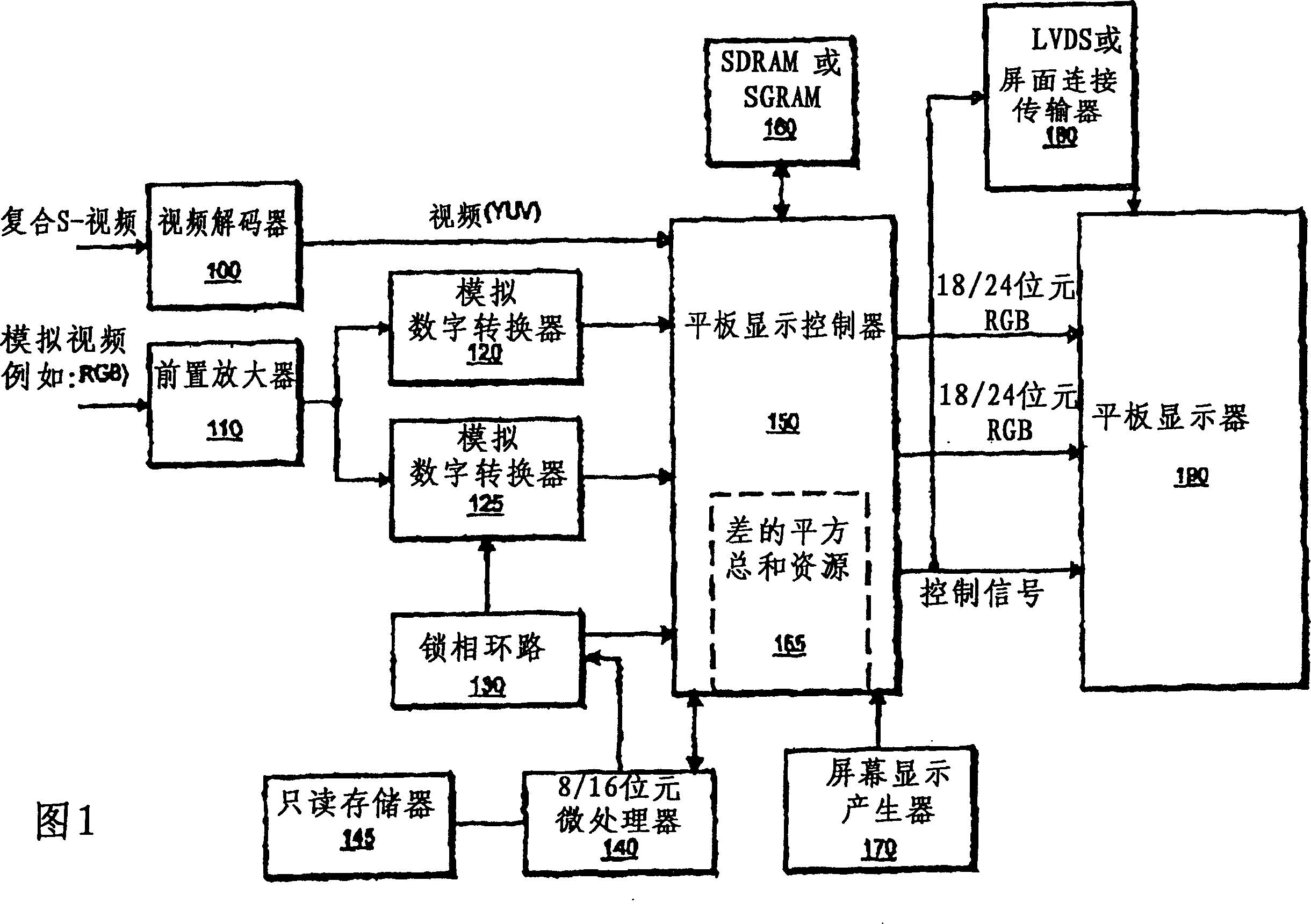
[0014] The preferred embodiment of the present invention can be seen from the environment in which it is applied. Figure 1 shows an embodiment of the present invention in which the resources for computing the sum of squared differences have been incorporated into the flat panel display controller. The figure again represents an environment where detection of input frequency and phase shift angle is important. Detecting the characteristics of these input signals is important because neither signals such as red-green-blue (RGB) signals nor composite S-Video signals have information to identify the input frequency. The importance of detecting the phase shift angle of an input signal is well known. Phase-locked loop (PLL) devices have been used to match two signals. However, PLL devices are used within a narrower frequency range. Apparatus and methods for detecting input frequency and phase facilitate controlling a PLL device.

[0015] In Figure 1, two types of input signals a...


PUM


Abstract

The design and processing method to detect the frequency and phase shift of input signal includes one or several samplers to response the clock signal to sample input signal. The number for each sample is determined and the sample difference value is calculated, and the difference value is self-multiplied with the products being accumulated. The sample is carried out to the data set of various clock signal, and the variance sum of the response to the frequency and phase shift of the input signal is selected.

Description

technical field [0001] The present invention relates to a device and method for detecting the frequency and phase shift of an input signal. The device applies time-domain methods to control a clock signal used to sample an input signal and detect its frequency and phase. Background technique [0002] Automatic tracking for real-time video applications consists in automatically tracking the frequency and phase shift angle of the analog input signal. Some solutions are found in frequency domain methods, such as fast Fourier transform (hereinafter referred to as FFT), discrete cosine transform (hereinafter referred to as DCT) or wavelet (wavelet). However, these frequency domain methods are expensive to implement in hardware. Furthermore, because of the computational complexity of these frequency domain methods, it is usually not practical to analyze the entire data screen for automatic tracking. Frequency-domain methods often only analyze a small portion of the entire scree...

Claims


Application Information

Patent Timeline
Patent Type & Authority Patents(China)
IPC IPC(8): H03L7/00H04N9/64H04N17/02
CPCG11B20/10037G11B20/1024
Inventor 李明志王福吉张华麟单培明
Owner MAGIC PIXEL
Why Eureka
Try Eureka