Supercharge Your Innovation With Domain-Expert AI Agents!

Terminal structure of electric cable and treating method thereof

A technology of end structure and end treatment, applied in the direction of coaxial cable/analog cable, cable terminal, electrical components, etc., can solve the problems of differential transmission signal line characteristic impedance mismatch, multiple working hours and cost, signal reflection, etc. , to achieve low cost, reduce reflection, and achieve the effect of impedance matching

Inactive Publication Date: 2005-10-12
TYCO ELECTRONICS JAPAN GK
View PDF2 Cites 2 Cited by
  • Summary
  • Abstract
  • Description
  • Claims
  • Application Information

AI Technical Summary

Problems solved by technology

Therefore, there is a problem that the characteristic impedance of the exposed differential transmission signal line does not match, and phenomena such as signal reflection and signal misalignment occur.
In addition, the processing of the end consumes more man-hours and costs

Method used


Image

  • Terminal structure of electric cable and treating method thereof
  • Terminal structure of electric cable and treating method thereof
  • Terminal structure of electric cable and treating method thereof

Examples


Embodiment Construction

[0022] Below, the best implementation forms of the cable end structure and the electric cable end treatment method of the present invention will be described in detail with reference to the accompanying drawings.

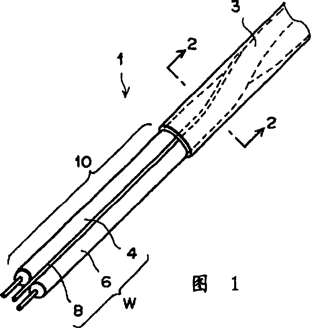
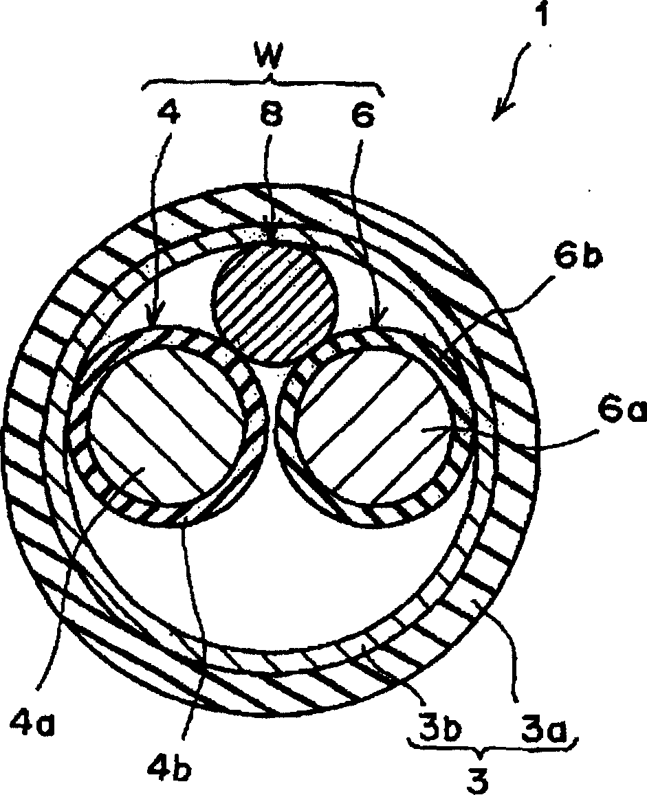
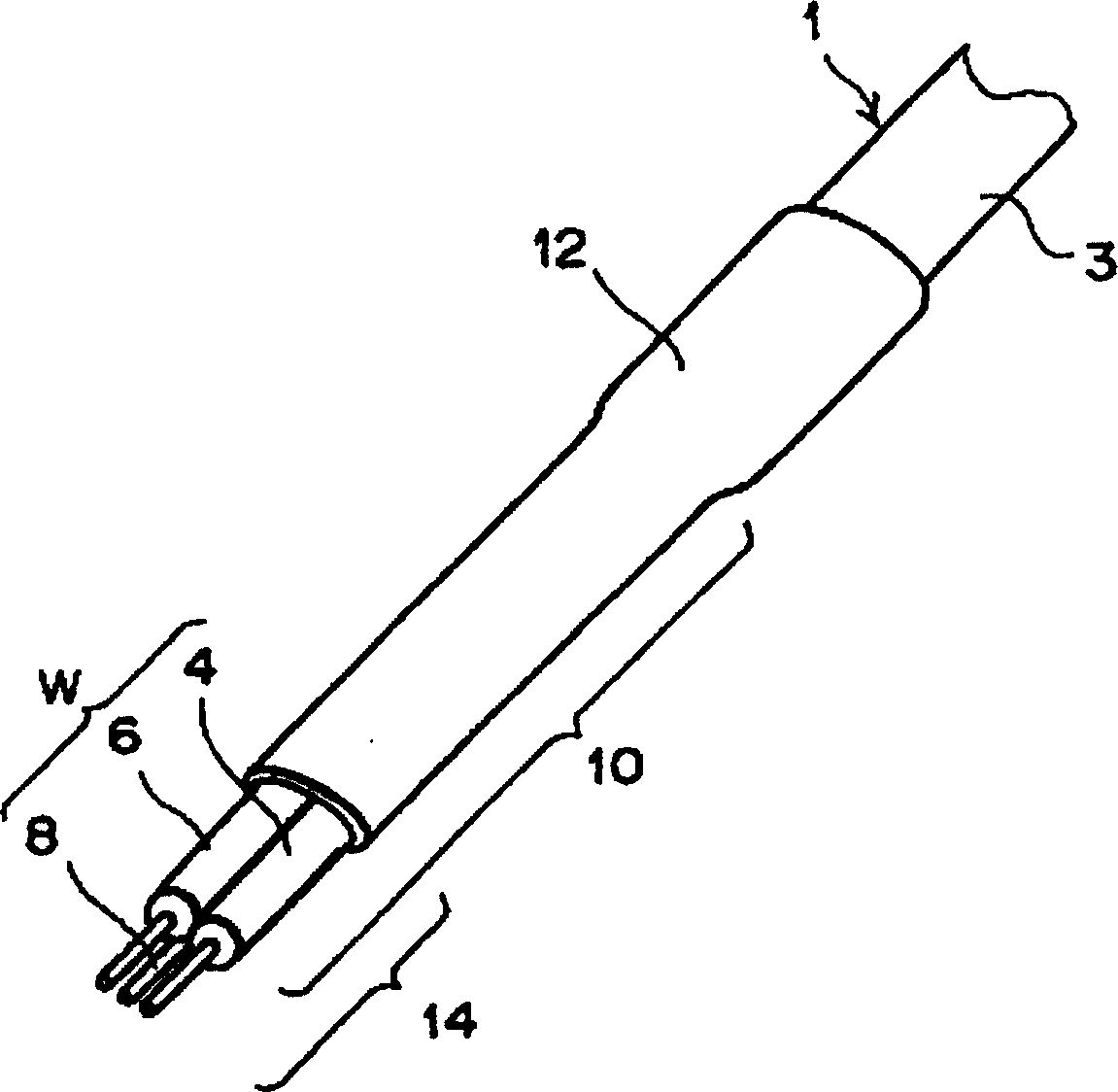
[0023] Fig. 1 is a perspective view of an end portion of an electric cable (hereinafter simply referred to as a cable) adopting the cable end structure of the present invention, showing the condition after part of the shielding coating is stripped off. figure 2 It is a 2-2 cross-sectional view of the cable showing a cross-section taken along the 2-2 line at the end of the cable shown in FIG. 1 . image 3 It is the perspective view similar to FIG. 1 after the end part of the cable shown in FIG. 1 is tightly covered with the heat-shrinkable tube.

[0024] Below, combined with Figure 1 to image 3 Be explained. As shown in FIG. 1 , generally, the cable 1 is a cable of the type called "shielded twisted pair cable" suitable for high-speed digital differential transmiss...


PUM


Abstract

The invention relates to an electrical cable (1) consisting of two differential transmission signal wires (4,6), a drain wire (8) and a shielding covering (3) which covers the wires and to a method of termination which minimizes the mismatching of the differential impedance of a terminal part (10) of the cable from which the shielding covering (3) has been stripped and the unstripped cable. Accordingly, a plastic heat-shrink tube (12) is adhered tightly to the terminal part (10) and the shielding covering (3), except for a stripped front end portion (14) of the terminal part (10), so that the front end portion (14) is exposed. As a result, the heat-shrink tube (12) prevents or alleviates the mismatching of the differential impedance.

Description

technical field [0001] The invention relates to an electric cable end structure and an electric cable end processing method, in particular to an electric cable end structure and an electric cable end processing method for high-speed signal transmission (high-speed digital differential transmission). Background technique [0002] In the past, as an example of the end structure of an electric cable (hereinafter referred to as a cable), the terminal treatment structure of a shielded wire disclosed in Japanese Patent Application Laid-Open No. 10-223051 and the terminal part of a coaxial cable disclosed in Japanese Patent Publication No. 56-24447 The forming method is already known. The terminal treatment structure of the former is a structure in which the middle part of two sheet-shaped shielded wires is tightly bound by a tape or a heat-shrinkable tube to form one, and the two ends exposed for branching are closed by each wire itself. The shielding layer is shielded. [0003]...

Claims


Application Information

Patent Timeline
Patent Type & Authority Patents(China)
IPC IPC(8): B29C63/18H01B7/00H01B7/17H01B11/06H01B11/18H01R9/03H01R9/05H02G1/14H02G3/04H02G15/02
CPCH02G3/0462H01R9/035H01R9/034H01R2103/00H01R24/44H01R9/0515H01R13/65914H01R13/65915H01B11/18
Inventor 相泽正幸内藤岳树
Owner TYCO ELECTRONICS JAPAN GK
Features
  • R&D
  • Intellectual Property
  • Life Sciences
  • Materials
  • Tech Scout
  • Unparalleled Data Quality
  • Higher Quality Content
  • 60% Fewer Hallucinations
Learn More