
Conic portion and neck sealing body for projecting tube

A sealing body and cone technology, applied in the sealing body field, can solve the problems of reducing the applied accelerating voltage, reducing the luminous brightness of the phosphor, and degrading the image quality, and achieving the effect of suppressing the deflection electric power

Inactive Publication Date: 2005-11-02
NIPPON ELECTRIC GLASS CO LTD
View PDF0 Cites 0 Cited by
  • Summary
  • Abstract
  • Description
  • Claims
  • Application Information

AI Technical Summary

Problems solved by technology

[0008] The horizontal deflection electric power is directly proportional to the inner diameter of the deflection yoke and the applied voltage of the electron gun, and is inversely proportional to the length of the deflection yoke. Therefore, in order to reduce the horizontal deflection electric power, it is envisaged to either reduce the applied acceleration voltage, or reduce the horizontal deflection frequency, or reduce the Inner diameter, or lengthen the length of the deflection yoke in the direction of the tube axis, but reduce the external acceleration voltage because the energy of the electrons of the electron beam hitting the phosphor decreases, so it will not only reduce the luminous brightness of the phosphor, but also reduce the horizontal deflection frequency decrease in image quality
Moreover, if the inner diameter of the deflection yoke is reduced, the outer diameter of the neck tube must be reduced, so the diameter of the electron lens in which the electron gun is installed has to be reduced, so that the focusing accuracy required in the aforementioned projection tube is reduced, and the deflection yoke The extension of the length will naturally make the above-mentioned projection tube larger

Method used


Image

  • Conic portion and neck sealing body for projecting tube
  • Conic portion and neck sealing body for projecting tube
  • Conic portion and neck sealing body for projecting tube

Examples


Embodiment Construction

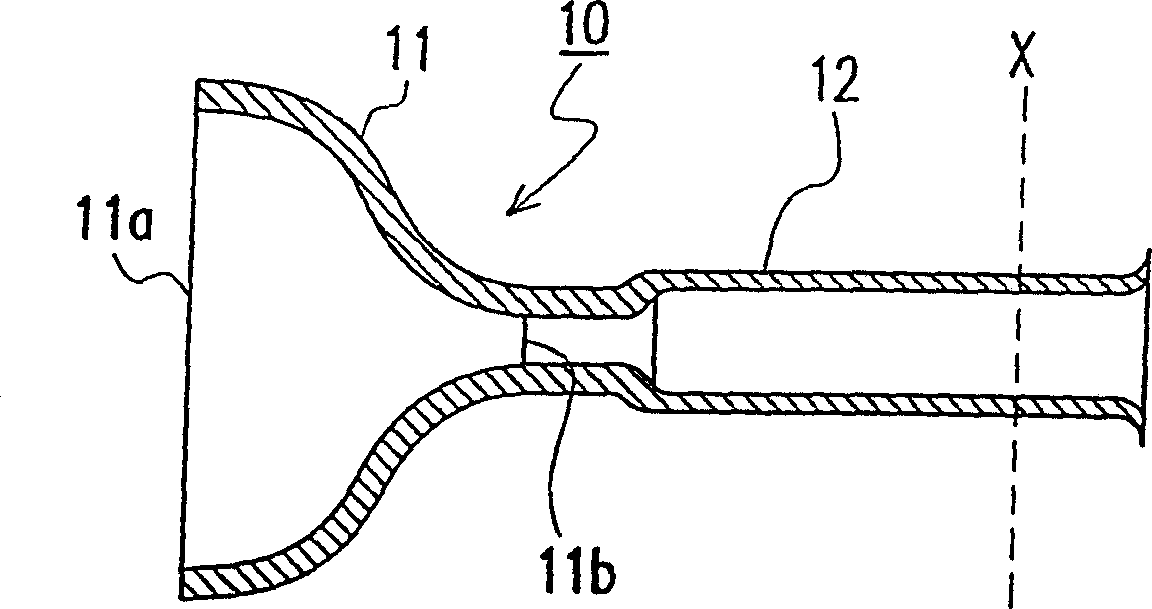
[0025] Refer below Figure 1 to Figure 6 , to illustrate the embodiments of the present invention.

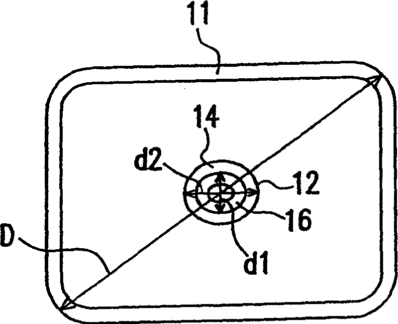
[0026] The composition of the projection tube cone and the neck sealing body 10 includes: a funnel-shaped cone 11 with a substantially rectangular large opening 11a and a circular small opening 11b; A cylindrical neck tube 12 .

[0027]On the substantially rectangular large opening 11a of the cone 11, since the panel 18 for the projection tube is installed later, the diagonal outer diameter D of the large opening rear portion 11a of the cone 11 is the diagonal outer diameter of the panel 18 for the projection tube. The same size is 175mm.

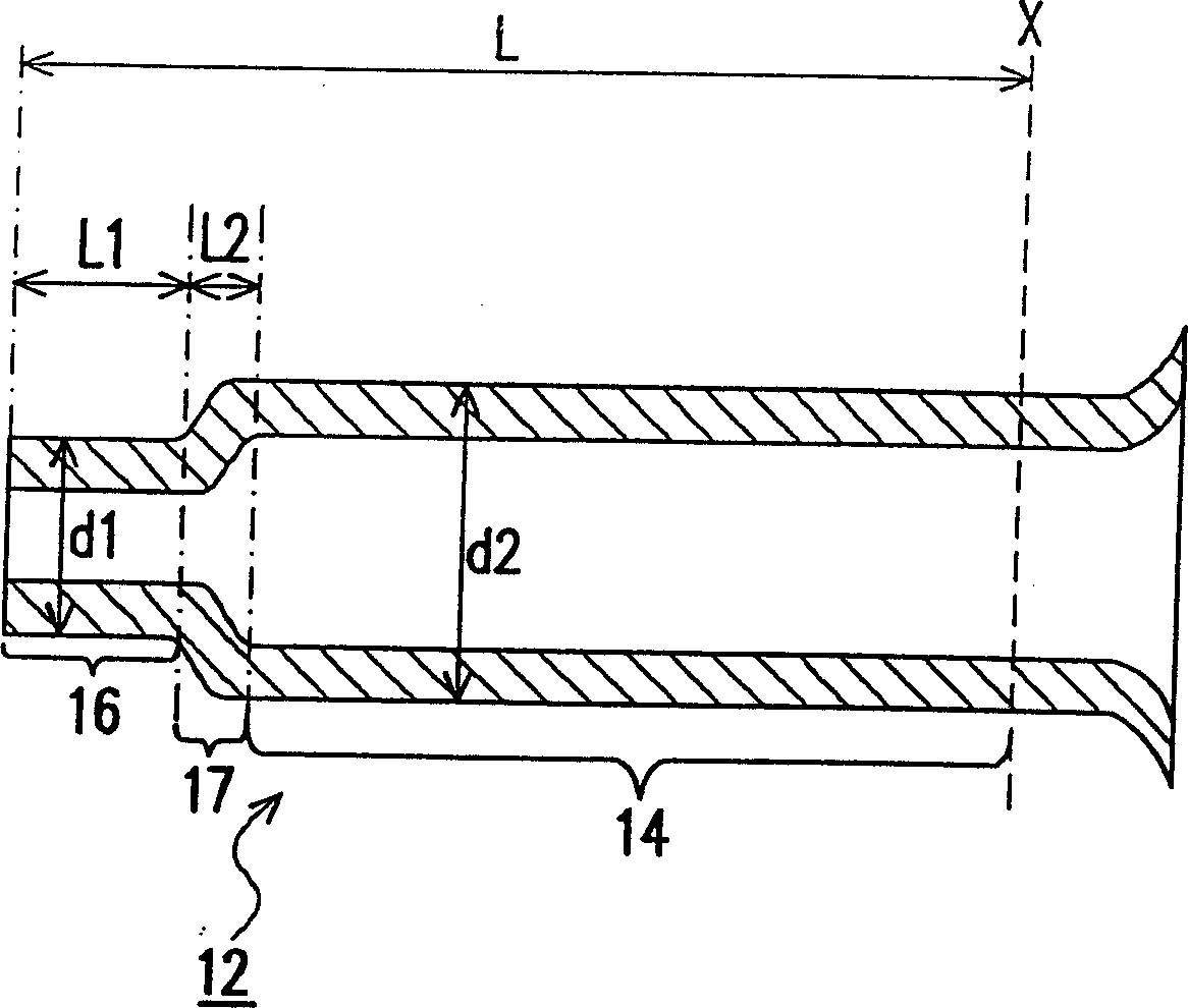
[0028] The neck tube 12 has an electron gun installation area 14 for installing an electron gun 13 inside and a deflection coil installation area 16 for installing a deflection coil 15 outside. The glass wall thickness of the neck tube 12 is 2.5mm, and the outer diameter d1 of the deflection coil installation area 16 is 29.1 mm. mm, and t...


PUM


Abstract

A funnel-and-neck sealing body comprises a funnel having a substantially rectangular large opening to which a panel for projection tube is sealed, and a circular small opening; and a neck tube of substantially a cylindrical shape sealed to the small opening of the funnel. The neck tube has an electron gun installing region for installing an electron gun therein, and a yoke mounting region for mounting a deflection yoke externally thereon, wherein an outer diameter of the yoke mounting region is smaller than an outer diameter of the electron gun installing region.

Description

technical field [0001] The present invention relates to a closure for the cone and neck of a projection tube. Background technique [0002] Such as Image 6 As shown, the glass member constituting a cathode ray tube (hereinafter referred to as a projection tube) for a projection tube (emission) is composed of a panel 30 coated with a phosphor inside, a neck tube 32 with an electron gun 31 built in, and a connecting panel 30 and the neck tube 32. The funnel-shaped cone 33 is formed, and these components are formed by using fritted glass, or the glass components themselves are fused to form a sealed glass vacuum tube 34 . [0003] The inside of the glass vacuum tube 34 becomes a high vacuum state in order to fly electrons from the electron gun 31. At the same time, a deflection yoke 35 is installed on its outside through the neck tube 32 and the cone 33, and the electron beam emitted from the electron gun 31 is controlled by the deflection coil 35. The electron beam hits the ...

Claims


Application Information

Patent Timeline
Patent Type & Authority Patents(China)
IPC IPC(8): H01J9/26H01J29/86H01J31/10
CPCH01J2229/8606H01J29/861H01J2229/8907H01J9/26
Inventor 洼阪卫江田道治
Owner NIPPON ELECTRIC GLASS CO LTD
Learn More