
Optical disc device

An optical disc device and optical disc technology, applied in the direction of recording information storage, instruments, etc., can solve the problems that the disc tray cannot be locked, cannot be used, and the recording of information is interrupted, so as to achieve the expansion of effective installation area, high safety and high density Effect

Inactive Publication Date: 2005-11-09
TEAC CORP
View PDF0 Cites 0 Cited by
  • Summary
  • Abstract
  • Description
  • Claims
  • Application Information

AI Technical Summary

Problems solved by technology

[0010] Once the above-mentioned state occurs, the disc tray will become unable to be locked and stored in the computer body, which means that it becomes unusable on the spot, and important work such as recording information through the computer is interrupted.

Method used


Image

  • Optical disc device
  • Optical disc device
  • Optical disc device

Examples


Embodiment Construction

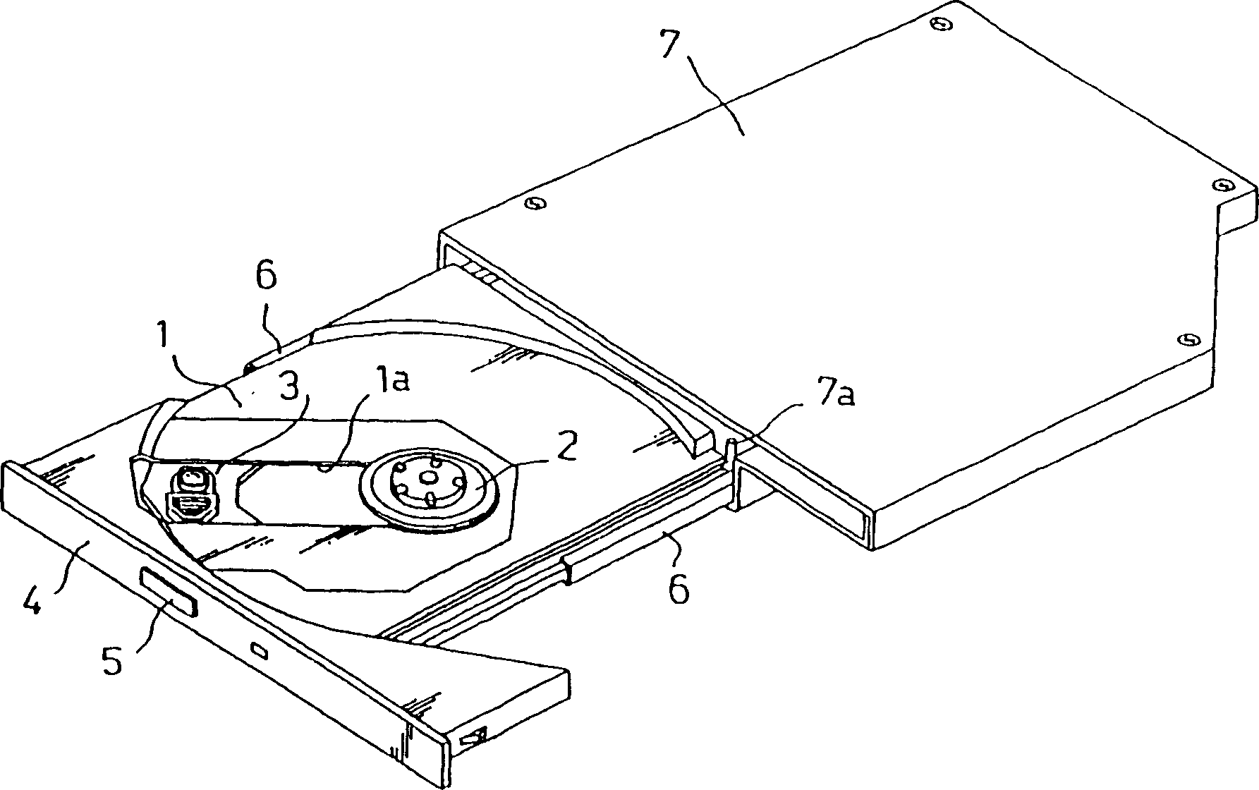
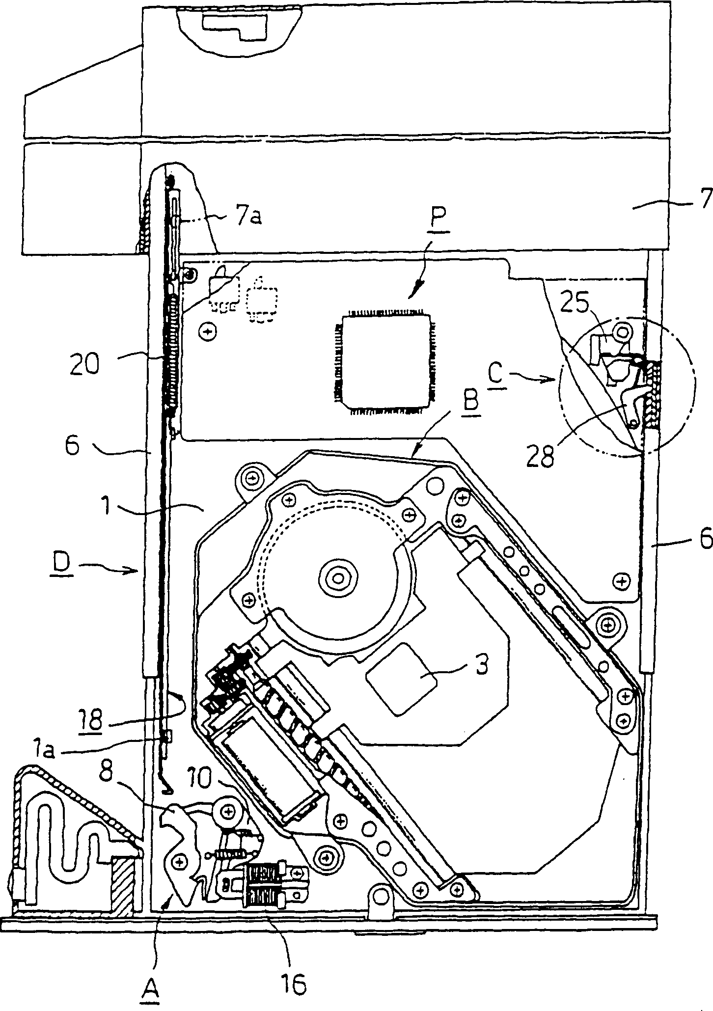
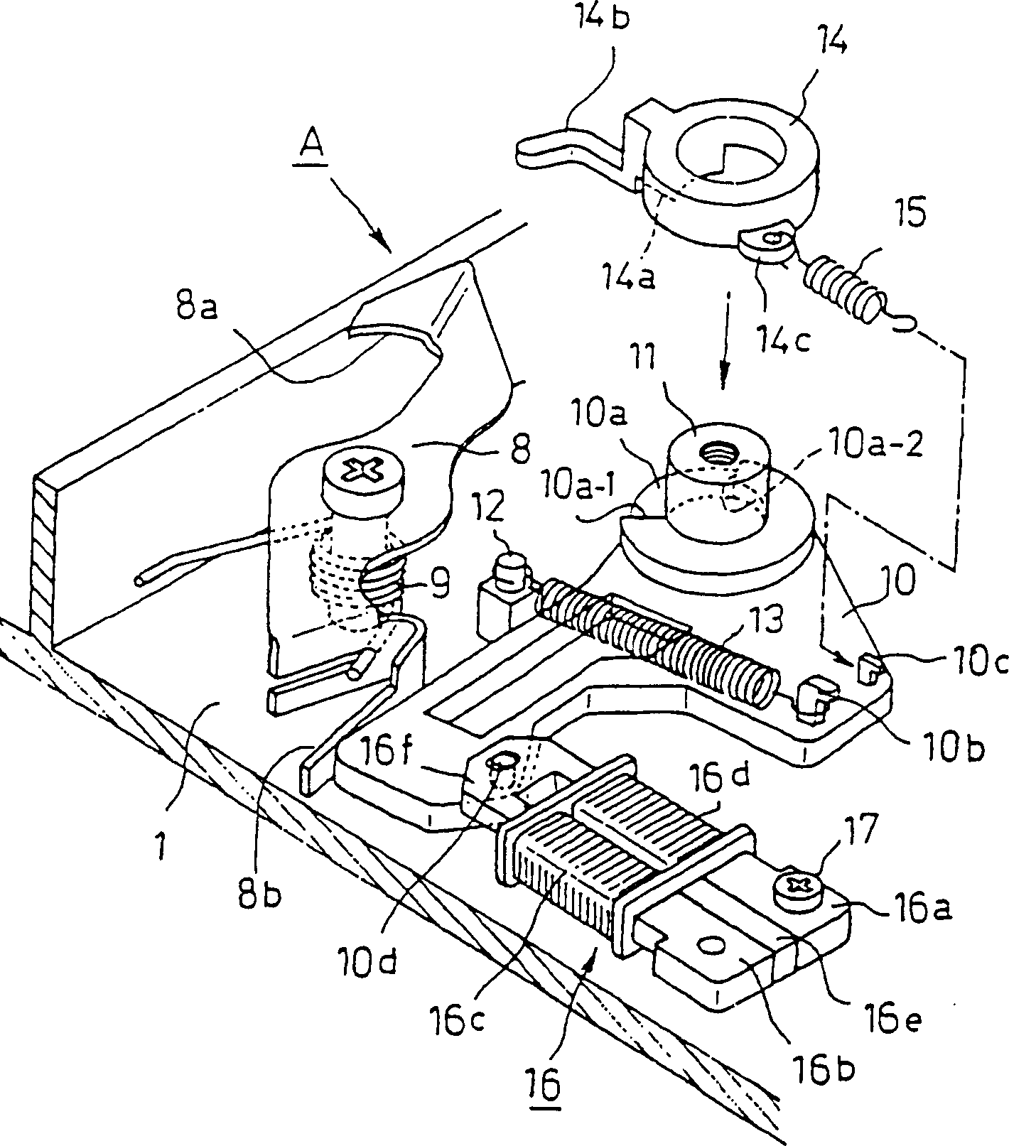
[0031] Hereinafter, embodiments of the present invention will be described in detail based on the drawings. In addition, in the embodiments described below, although the object is based on the premise that the optical disc device is mounted in the computer body, the present invention is not limited thereto, and an external optical disc device can also be implemented. In addition, although the locking mechanism of the present invention is described as being implemented on an optical disc tray of an optical disc device, the desired object can be achieved even if it is implemented on a case that accommodates an optical disc tray.

[0032] figure 1 It is a schematic diagram of the appearance of the optical disc device D implemented by the present invention, in figure 1 Among them, a component symbol 1 represents an optical disc tray, and a turntable 2 for rotationally driving an optical disc is provided at the center thereof. Then, a window 1a is formed at the disc tray 1, and...


PUM


Abstract

The objective of the invention is to provide a optical disk device, load / unlod with a recording medium by making a disk tray advance and retreat in a chassis case, wherein an eject / lock mechanism operating together with a self-holding type solenoid is arranged in the front edge corner portion of the disk tray and, on the other hand, a start lever that changes over the eject / lock mechanism to the lock state extends along a sidewall of the disk tray, a lock lever that can swing and fit with the chassis case is provided on the disk tray so that the oscillation of the lock lever be inhibited when the disk tray receives the impact load in the load state. Thereby the apparatus of the invention can prevent the disk tray daping to raise safety and reliance, and extend an mount effective area of a wiring board.

Description

technical field [0001] The present invention relates to an optical disc device for driving an optical disc (for example, CD-R / RW, DVD-R / RW, etc.) as a recording medium for recording a large amount of information in various computer systems and the like. Background technique [0002] In general, in a personal computer (hereinafter referred to as a computer), an optical disk device is indispensable for recording and reproducing information on an optical disk, and is installed in the computer itself or connected with a cable by a so-called external connection. . [0003] Figure 7(A) is a schematic view of the appearance of a notebook computer equipped with an optical disc device. Generally, the optical disc device D is mounted on one side of the computer body, and the baffle plate of the optical disc tray 101 is opened by a switch operation or an order issued by the computer. The part of 102 is ejected, and then the user of the computer can pull out the disc tray and load the ...

Claims


Application Information

Patent Timeline
Patent Type & Authority Patents(China)
IPC IPC(8): G11B17/04
CPCG11B17/056
Inventor 椛泽秀年
Owner TEAC CORP
Learn More