
Large-scale three dimensional shape and appearance measuring and splicing method without being based on adhesive mark

A topography measurement and marking technology, applied in the field of precision measurement, can solve the problems of destroying the characteristics of the measured topography, increasing automatic identification errors, affecting the authenticity of the measurement, etc. Effect

Inactive Publication Date: 2005-12-28
TIANJIN UNIV
View PDF0 Cites 0 Cited by
  • Summary
  • Abstract
  • Description
  • Claims
  • Application Information

AI Technical Summary

Problems solved by technology

[0005] The above method has obvious limitations: 1) For the appearance measurement of large objects, many marking points must be set, which is very cumbersome, and as the number of marking points increases, the error of automatic recognition increases; 2) A large number of marking points must be pasted on the measured object surface, which destroys the characteristics of the measured shape and affects the authenticity of the measurement

Method used


Image

  • Large-scale three dimensional shape and appearance measuring and splicing method without being based on adhesive mark
  • Large-scale three dimensional shape and appearance measuring and splicing method without being based on adhesive mark
  • Large-scale three dimensional shape and appearance measuring and splicing method without being based on adhesive mark

Examples


Embodiment approach

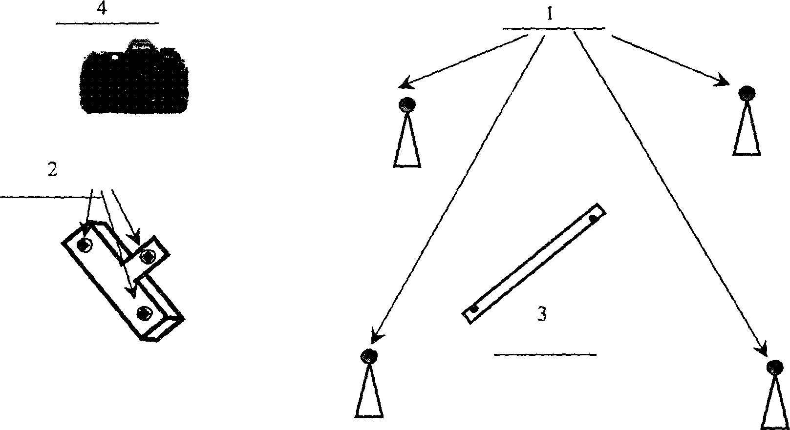
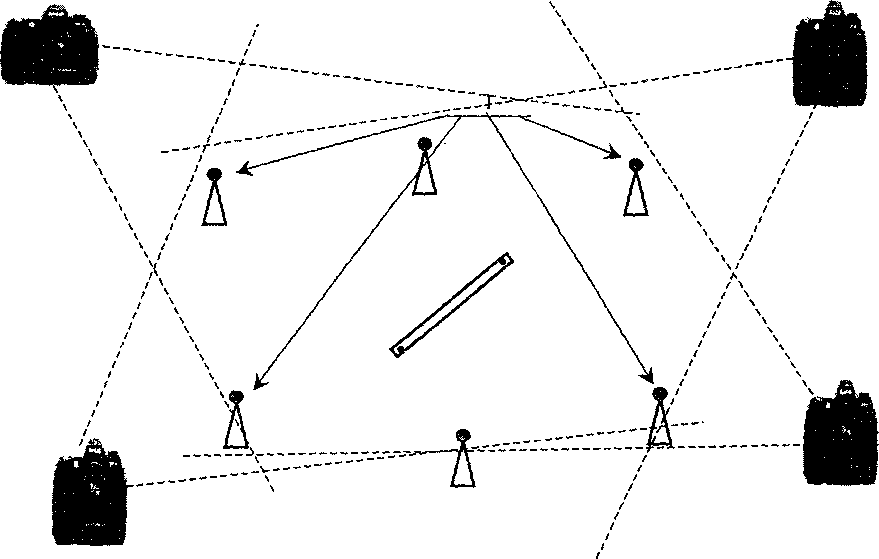
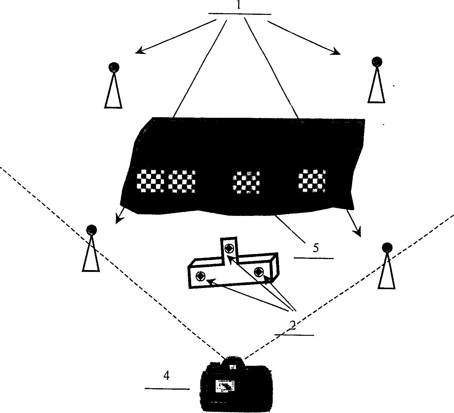
[0022] like figure 2 As shown, more than 4 global control points are placed in the measured space. The number of global points can be determined according to the actual requirements (the size of the measured object). The global control points are positioned at the center of the precision sphere. Three (or more) probe control points are fixed on the optical probe, and the probe control points are positioned by the center of a precision sphere or the center of a plane circle. The coordinates of the control points on the probe in the probe measurement coordinate system are pre-calibrated.

[0023] When measuring, first, use a digital camera to take images containing all global control points from multiple angles, and obtain the global control points in the global coordinate system O g x g Y g Z g The spatial coordinate value in; secondly, the optical probe measures each area of ​​the measured object one by one, and in measuring each area S i when, such as image 3, use a d...


PUM


Abstract

The invention discloses a splicing method for large-scale three-dimensional body shape measurement not based on sticky marks, which converts the measurement data of each local position of the probe into the global coordinate system through the control points of the probe, and realizes splicing from local to whole. The stitching method includes: placing a reference ruler marked with two marker points in the measurement space; using a high-resolution digital camera to take images containing the global marker point and the reference ruler from multiple different angles and different attitudes; An image containing the control points of the probe and at least 3 global control points; for each area, the measurement data of the probe is transformed into the global coordinate system, so that the measurement data of each measurement area are unified into the global coordinate system , to complete the splicing of single area measurement data to the whole. The invention does not need to paste multiple marking points on the surface of the measured object, does not affect the characteristics of the measured shape itself, the measured data is true and reliable, and the operation is simple and efficient.

Description

technical field [0001] The invention relates to a precision measurement method, in particular to a splicing method for measuring the shape of a large object (body) not based on sticky marking points. Background technique [0002] Body shape measurement refers to the measurement of the surface shape of the body. It is the basic support technology for modern reverse engineering and product digital design, management and manufacturing. It is also an advanced product testing method. It has a wide range of application backgrounds in the field of advanced manufacturing. has drawn people's attention. [0003] Traditionally, there are two main types of schemes for realizing shape measurement: direct use of coordinate measuring machine (CMM) and indirect use of CMM measurement principles. The former directly applies the CMM, puts the object to be measured on the CMM, samples the object with the CMM probe, and obtains the shape data of the object. However, due to the limitation of th...

Claims


Application Information

Patent Timeline
Patent Type & Authority Patents(China)
IPC IPC(8): G01B11/03G01B11/24G01B21/04G01B21/20
Inventor 邾继贵吴斌刘常杰
Owner TIANJIN UNIV
Learn More