Method for iron core lamination of electric machine and lamination structure thereof

A core lamination and lamination technology, applied in the field of iron core lamination, can solve the problems of complex manufacturing process, low productivity, time-consuming, etc.

Inactive Publication Date: 2006-03-01
LG ELECTRONICS INC
View PDF0 Cites 2 Cited by
  • Summary
  • Abstract
  • Description
  • Claims
  • Application Information

AI Technical Summary

Problems solved by technology

[0012] However, according to the prior art, the laminated bodies of the laminated sheets L are fixed and connected by welding, so the manufacturing process is complicated and time-consuming, and the productivity is very low.

Method used


Image

  • Method for iron core lamination of electric machine and lamination structure thereof
  • Method for iron core lamination of electric machine and lamination structure thereof
  • Method for iron core lamination of electric machine and lamination structure thereof

Examples


Embodiment Construction

[0033] Preferred embodiments of the present invention shown in the accompanying drawings will be described in detail below.

[0034] The first embodiment of the motor core lamination method and lamination structure according to the present invention will be described below.

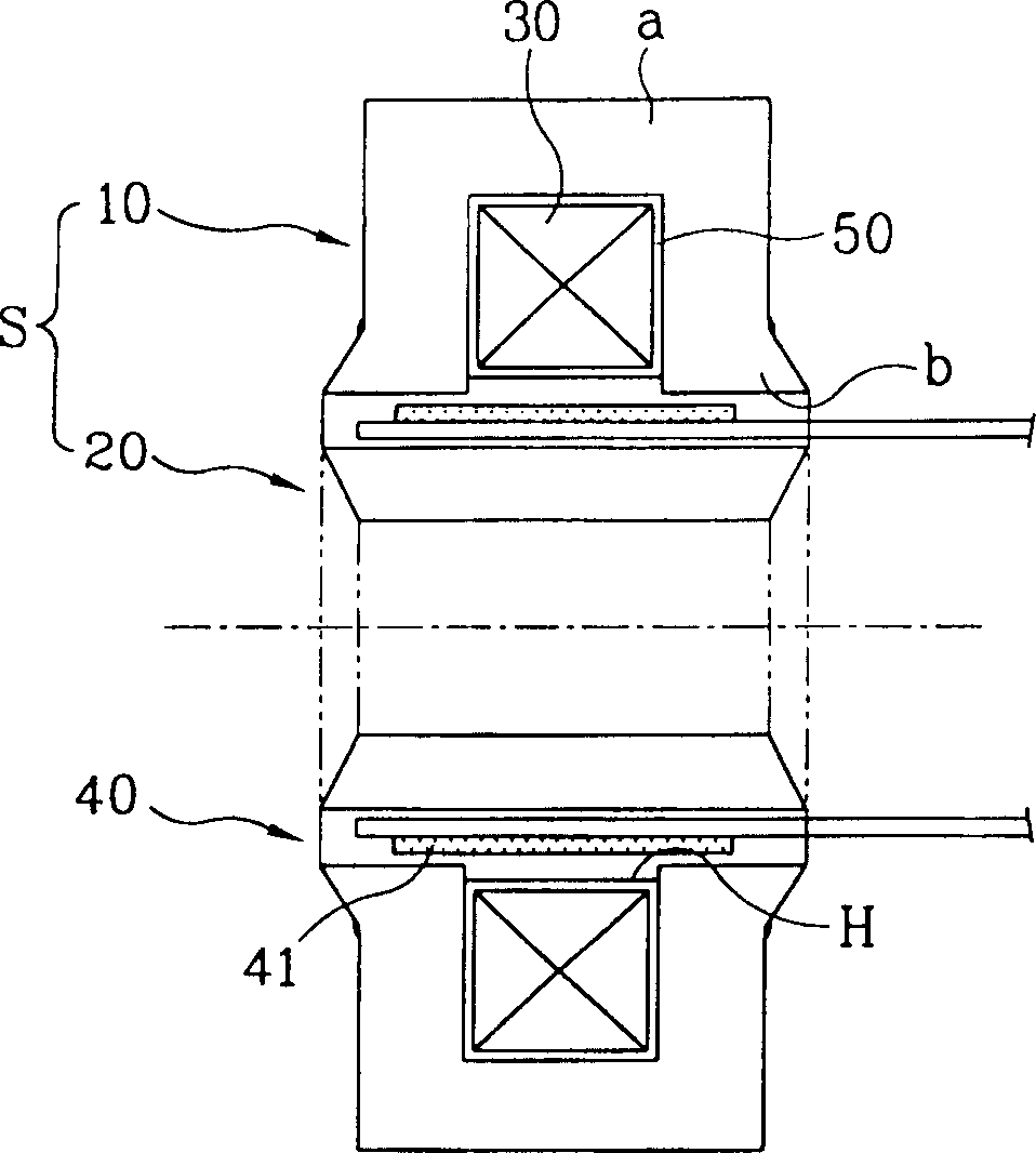
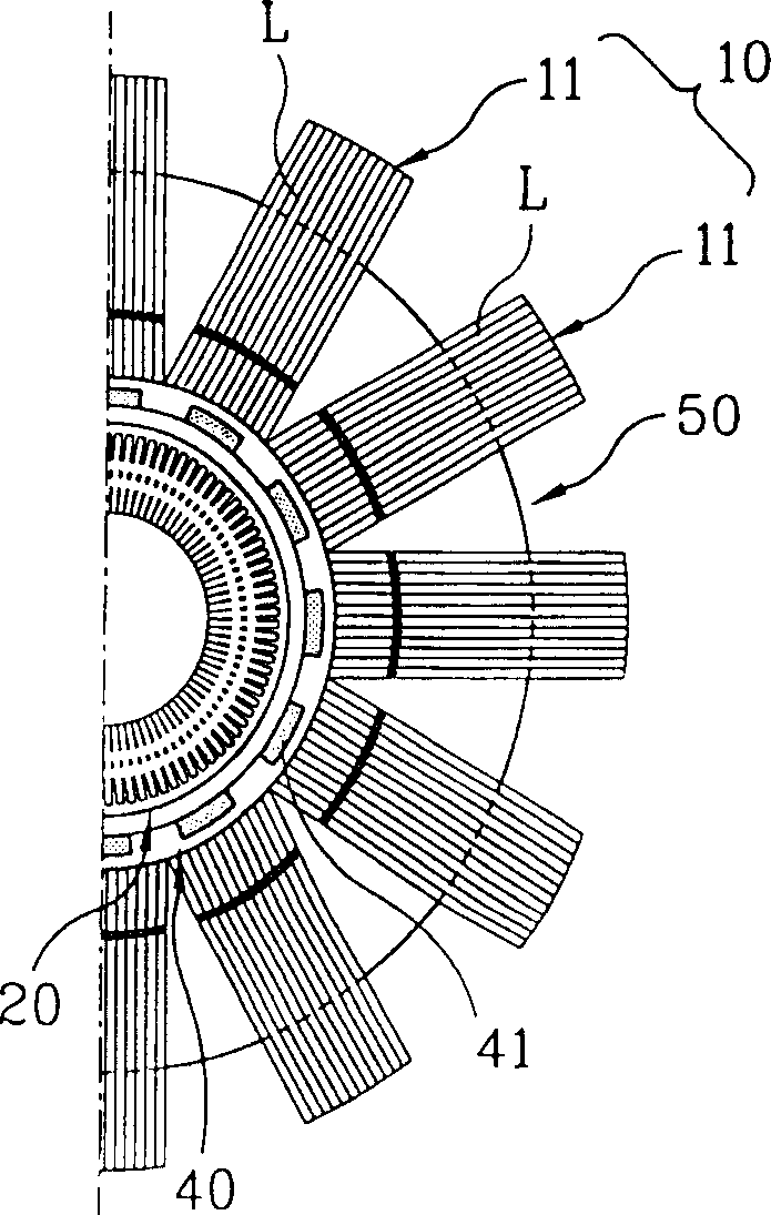
[0035] Figure 4 with Figure 5 An embodiment of an electrical machine incorporating an electrical machine lamination according to the invention is shown. As shown in the figure, the motor includes: a stator (S), which includes an outer core 100 and an inner core 20, the inner core 20 being a cylinder, inserted in the outer core 100; winding coils 30, connected inside the outer core 100 or the inner core 20 the inner side; and an armature 40 which includes a permanent magnet and is inserted between the outer core 100 and the inner core 20 to move. In the drawing, the winding coil 30 is connected inside the outer core 100 .

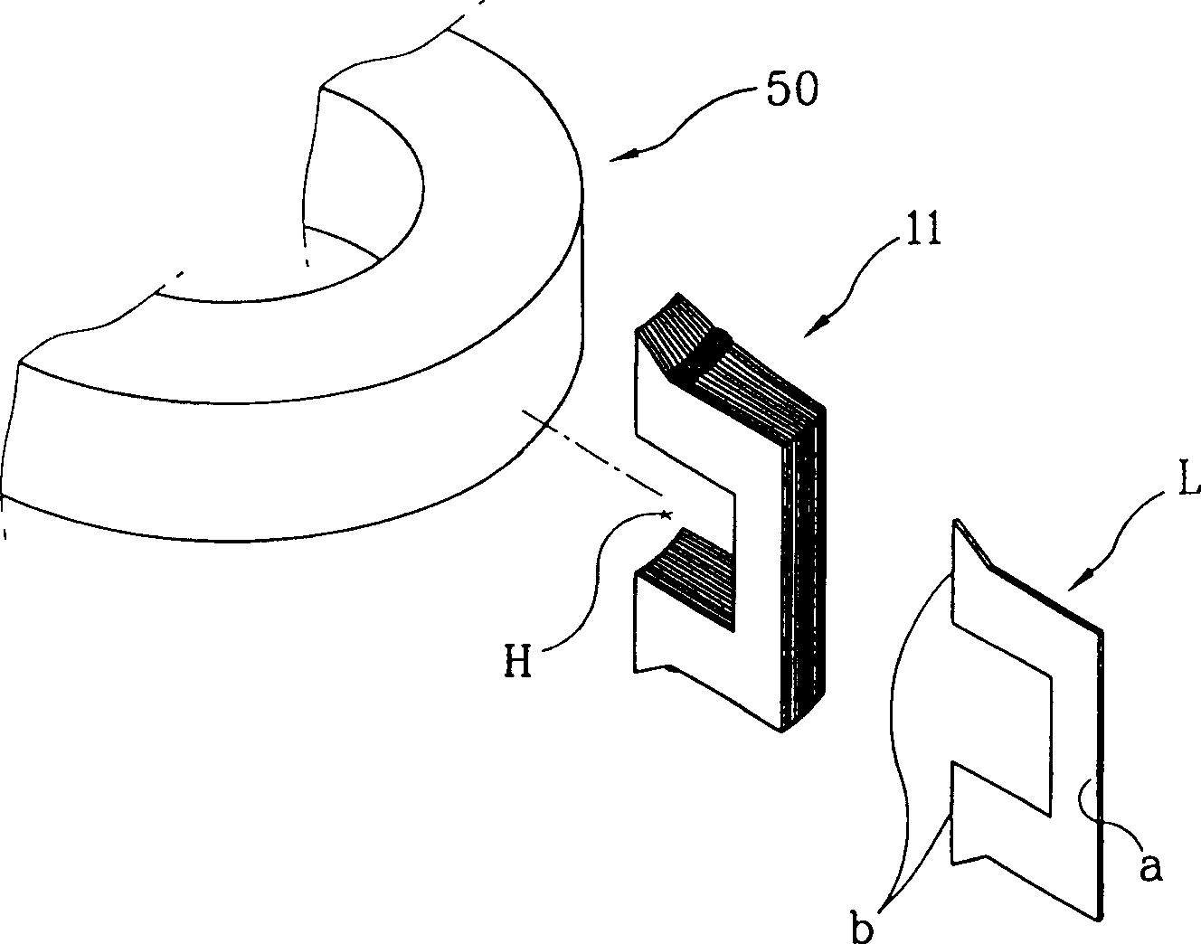
[0036] In addition, the outer core 100 included in the stator S is formed in ...


PUM


Abstract

A core lamination structure in a motor is constructed such that a plurality of lamination sheets of a predetermined shape are laminated to form a laminated body, that is, a unit lamination core. The unit lamination core formed by the plurality of lamination sheets is fixedly coupled by a caulking portion or a coupling portion formed on the respective lamination sheet and connected with the adjacent lamination sheets to be in a row. In this way, a fabricating process of the unit lamination core is made to be easy and simple to reduce time for fabricating, and a curvature for a curved surface portion of the unit lamination core can be changed so that the present invention can be applied to various motors according to the capacity or the size of the motor.

Description

technical field [0001] The present invention relates to a lamination method and a lamination structure of an iron core in a motor, in particular to a lamination method and a lamination structure of an electric motor core that enable the curvature of the lamination body to be changed and whose structure and manufacture are simpler, wherein the lamination The body is made by laminating a number of laminations and attached to the bobbin. Background technique [0002] Generally, reciprocating motors are made by changing the magnetic flux of a general-purpose motor with a spatial structure into a planar shape, that is, the moving part of the planar shape moves in accordance with the change of the magnetic flux formed on the fixed part of the plane Linear motion on a plane. [0003] figure 1 with figure 2 An example of a reciprocating motor is shown. As shown in the figure, the reciprocating motor includes: a stator S, which includes an outer core 10 and an inner core 20, the ...

Claims


Application Information

Patent Timeline
Patent Type & Authority Patents(China)
IPC IPC(8): H02K15/02H02K1/06H02K1/18H02K1/14H02K33/16
CPCH02K15/022H02K1/145H02K2201/09
Inventor 朴景培
Owner LG ELECTRONICS INC
Why Eureka
Try Eureka