Gravity type titable metal mold casting machine

A technology for casting machinery and metal molds, applied in the field of gravity-type tiltable metal mold casting machinery, can solve the problems of high metal lower mold height and difficult operation.

Inactive Publication Date: 2006-03-22
SINTOKOGIO LTD
View PDF0 Cites 2 Cited by
  • Summary
  • Abstract
  • Description
  • Claims
  • Application Information

AI Technical Summary

Problems solved by technology

Therefore, a large space must be prepared to install the machine
In addition, there is another problem in that the height from the machine's mounting surface to the metal lower die is large
This makes it difficult to put the core in the lower mold and take out the cast product

Method used


Image

  • Gravity type titable metal mold casting machine
  • Gravity type titable metal mold casting machine
  • Gravity type titable metal mold casting machine

Examples


Embodiment Construction

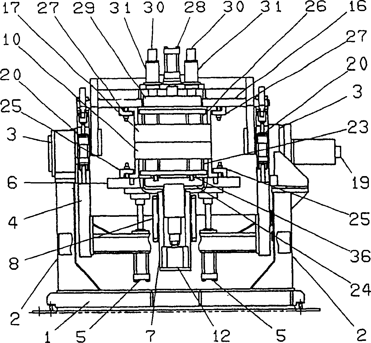
[0022] The embodiments of the present invention are described in detail below with reference to the accompanying drawings. in figure 1 with 2 A pair of relatively upright frames 2 and 2 are installed on the base 1. A pair of opposed main rotating shafts 3, 3 are arranged on the axis and rotatably mounted on the upper ends of the upright frames 2, 2. The main frame 4 is fixedly mounted on the main rotating shafts 3, 3 in such a way that the main frame hangs down from the main rotating shaft and is suspended between them. In order to reversibly rotate the main frame 4A, a main motor 19, such as a servo motor, is mounted on one of the supporting frames. A main motor 19 for reversibly rotating the main frame 4 is connected to one end of one of the main rotating shafts 3 and 3.

[0023] In order to fasten the mold, a number of upward facing cylinders 5 and 5 are installed in the lower part of the main frame 4. A lower template 6 is fixed to the ends of the piston rods of the mold clam...


PUM


Abstract

A gravity type tiltable metal mold casting machine, comprising: a pair of opposing upright supporting frames (2, 2); a pair of opposing main rotating shafts (3, 3) rotatably mounted on the upright supporting frames (2, 2); a main frame (4) suspended from and between the main rotating shafts (3, 3); an electric motor (19) attached to one of the main rotating shafts (3, 3) for reversibly rotating it and hence the frame (4); a drag die plate (6) vertically moved by mold-fastening cylinders (5, 5) mounted on a lower part of the main frame (4); a metal drag (10) secured to the drag die plate (6), the metal drag having a drag pushing-out mechanism (23) for pushing an as-cast product out of the metal drag; a pair of opposing horizontal cope tilting shafts (13, 13) secured to an upper end of the main frame at locations rearward of the main rotating shafts (3, 3); a cope-attaching frame (14) rotatably mounted at one end on the cope tilting shafts (13, 13); a cope die plate (16) secured to a lower surface of the cope-attaching frame (14); a metal cope (17) secured to the cope die plate (16), the metal cope having a cope pushing-out mechanism (26) for pushing an as-cast product out of the metal cope, a ladle (21) rotatably mounted about a horizontal axis of rotation, the horizontal axis of rotation being located rearward of the assembly of the metal cope and drag; and an electric motor (9) for reversibly rotating the ladle (21) about the horizontal axis of rotation, wherein the center of the assembly of the metal cope and drag is substantially on the axis of rotation of the main rotating shafts.

Description

Technical field [0001] The present invention relates to a gravity-type tiltable metal mold casting machine in which molten metal (for example, aluminum) is poured into a mold cavity formed by a metal upper mold and a metal lower mold when they are tilted. Background technique [0002] JPH 5-31809A discloses this traditional gravity type tiltable metal mold casting machine. This machine is constructed in such a way that the rotation of the entire casting machine and the rotation of the upper metal mold (that is, to release the upper opening of the lower metal mold) are both around a common axis (the rotation axis outside the assembly of the upper metal mold and the lower mold) And proceed. [0003] Since the axis of rotation of the machine and the axis of rotation of the upper metal mold are the same in this machine, the single axis of rotation must be outside the assembly of the upper metal mold and the lower mold, so that when the upper metal mold is opened, the upper part of th...

Claims


Application Information

Patent Timeline
Patent Type & Authority Patents(China)
IPC IPC(8): B22D23/00
CPCB22D23/006
Inventor 大杉光春成濑英次金山祐二村田裕
Owner SINTOKOGIO LTD
Why Eureka
Try Eureka