Universal positive emitter coupling logic/low voltage differential command output structure

A technology of signal transmission and output components, applied in the direction of logic circuit coupling/interface, logic circuit connection/interface layout, logic circuit, etc. using field effect transistors, which can solve the problems of inalterability, high cost, and large volume

Inactive Publication Date: 2006-03-22
NXP BV
View PDF0 Cites 0 Cited by
  • Summary
  • Abstract
  • Description
  • Claims
  • Application Information

AI Technical Summary

Problems solved by technology

However, this circuit has many disadvantages, including large size, high cost and inalterability, etc.

Method used


Image

  • Universal positive emitter coupling logic/low voltage differential command output structure
  • Universal positive emitter coupling logic/low voltage differential command output structure
  • Universal positive emitter coupling logic/low voltage differential command output structure

Examples


Embodiment Construction

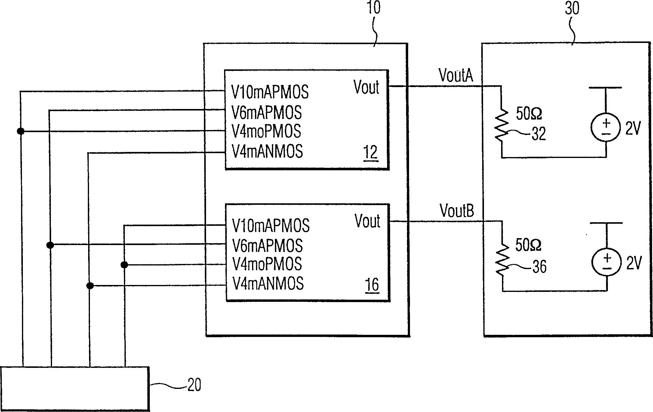
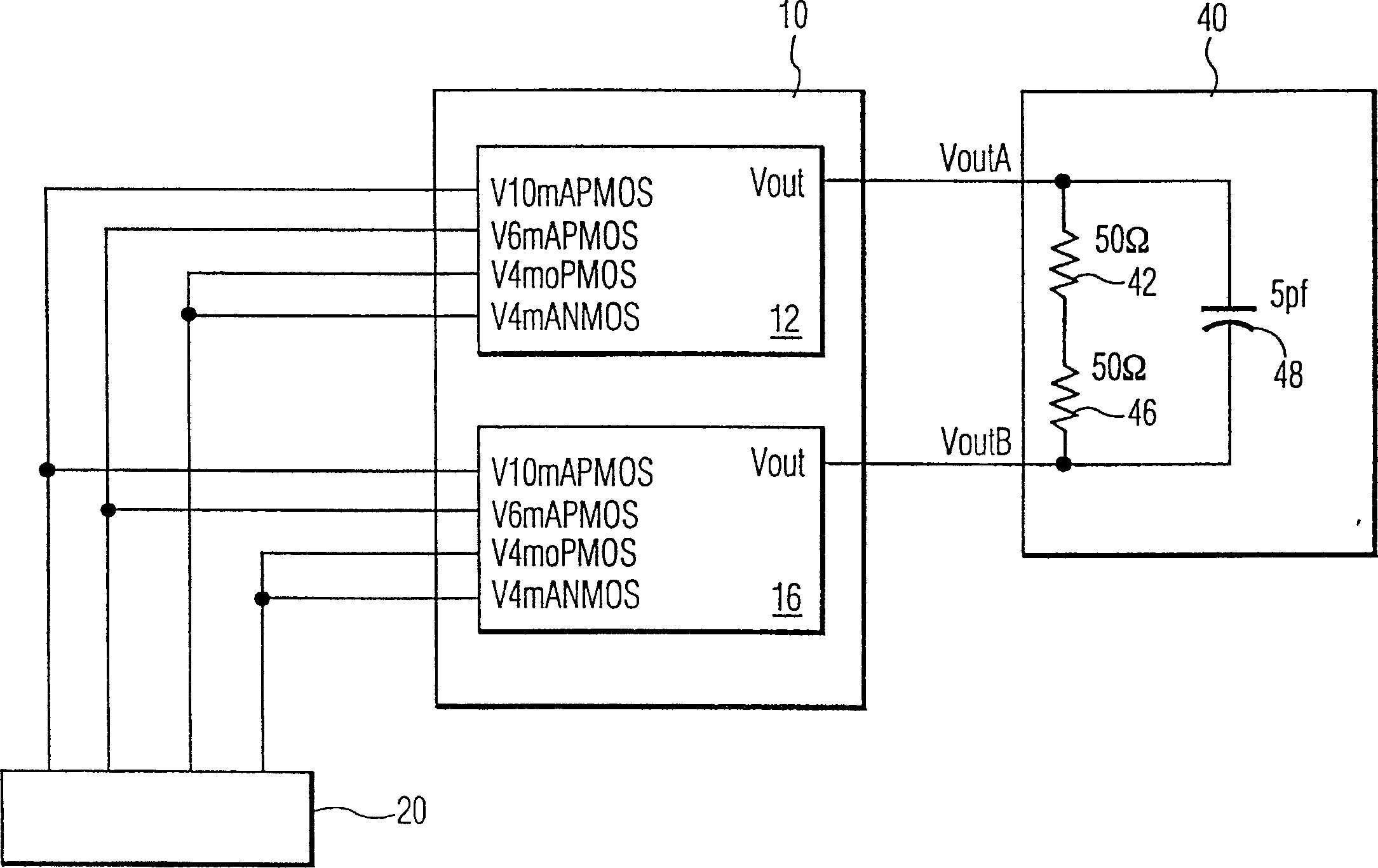
[0015] figure 1 A general-purpose front-emitter coupled logic / low voltage differential signaling output structure 10 configured to implement a front emitter-coupled logic output is shown in accordance with an embodiment of the present invention. figure 1 In , the output structure 10 is connected between the control logic 20 and a standard positive emitter coupled logic termination circuit 30 . The output structure 10 includes a first output component 12 and a second output component 16 . Each of the two output sections includes a switchable current source capable of supplying 4mA, 6mA, 10mA, or 20mA. Control logic 20 allows the user to switch output structure 10 (via outputs VoutA and VoutB) between two signaling methods, positive emitter coupled logic and low voltage differential signaling, by enabling specific circuitry for the respective signaling technology.

[0016] In configuring the output structure 10 to implement a positive emitter coupled logic output, the input si...


PUM


Abstract

The invention implements a Positive Emitter Coupled Logic (PECL) output using CMOS transistors that approximate the Motorola ECL characteristics into standard PECL termination schemes. By creating a PECL output using a switchable current source the PECL output can be integrated into a Low Voltage Differential Signaling (LVDS) structure. The invention allows the user to switch between PECL and LVDS outputs via control logic by enabling the specific circuit elements for each signaling technology. With this invention, the combination of two drivers on one IC device gives system designers the flexibility to use the same circuitry in two separate signaling schemes. Thus, the designers can select to use one output characteristics or the other for their designs.

Description

technical field [0001] The present invention generally relates to electronic equipment, and more specifically, relates to an output structure for a signal transmission method of positive emitter coupled logic / low voltage differential signal transmission [PECL (Motorola Positive Emitter Coupled Logic) / LVDS (Low Voltage Differential Signaling)]. Background technique [0002] In telecommunications and networking systems, signal transmission methods have been used to send signals from one device to another over a wire. Among the many high-speed signaling methods, forward-emitter-coupled logic and low-voltage differential signaling point-to-point techniques have been employed. Forward Emitter Coupled Logic is a standard developed by Motorola in which the output node voltages are Vdd-1 volts and Vdd-1.6 volts. Low voltage differential signaling, on the other hand, is the EIA-644 standard, where the output differential voltage swing is ±400mV. Many designers and manufacturers of ...

Claims


Application Information

Patent Timeline
Patent Type & Authority Patents(China)
IPC IPC(8): H03K19/0175H03K19/0185H03K19/0948
CPCH03K19/018585
Inventor J·A·维斯特小R·J·马沙尔A·安德森D·M·鲁泽布姆
Owner NXP BV
Why Eureka
Try Eureka