
Device for measuring pipe wall thickness in pipe press

A technology of measuring device and measuring tube, applied in the direction of measuring device, rolling mill control device, using optical device, etc., to achieve the effect of cheap realization and simple structure

Inactive Publication Date: 2006-03-29
SMS MEER
View PDF3 Cites 0 Cited by
  • Summary
  • Abstract
  • Description
  • Claims
  • Application Information

AI Technical Summary

Problems solved by technology

[0009] Therefore, the object of the present invention is such that the device of the above-mentioned type is perfected in such a way that the optimal working conditions of the laser-ultrasonic measuring device can be ensured under the situation of overcoming the above-mentioned difficulties.

Method used


Image

  • Device for measuring pipe wall thickness in pipe press
  • Device for measuring pipe wall thickness in pipe press
  • Device for measuring pipe wall thickness in pipe press

Examples


Embodiment Construction

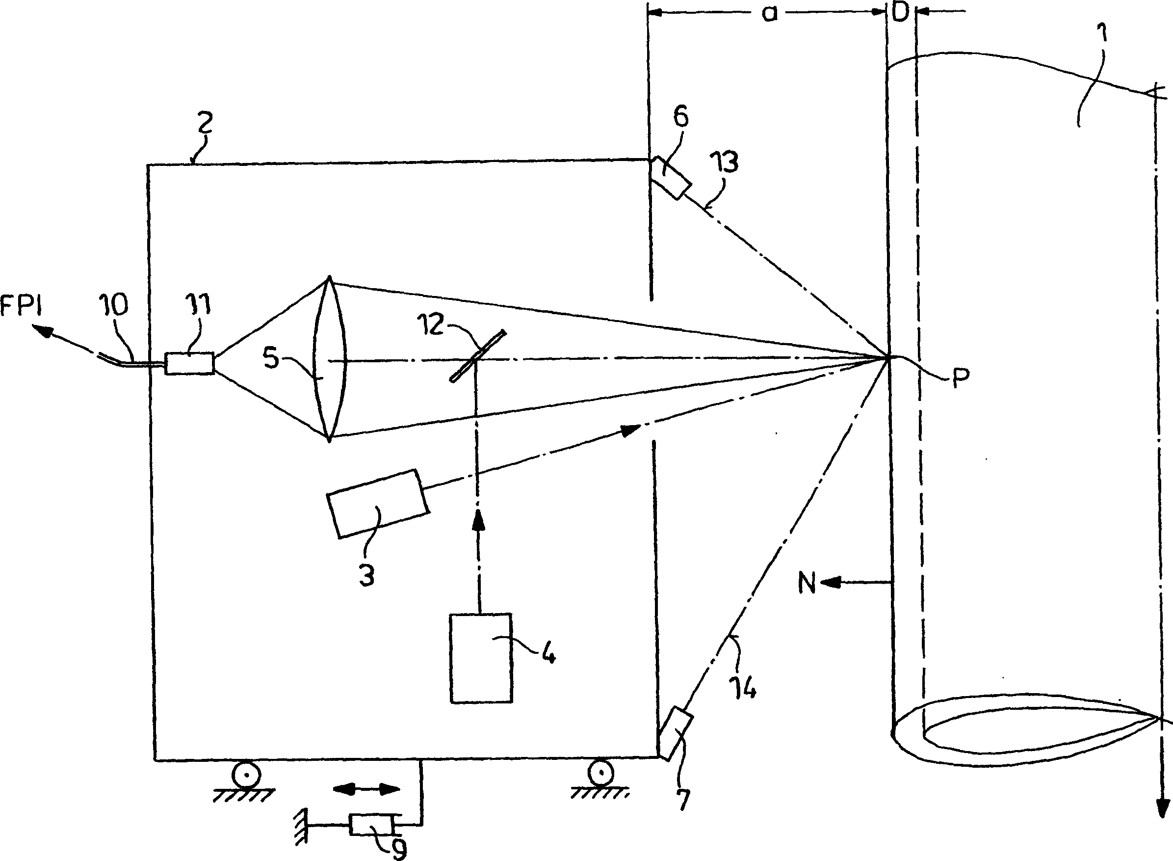
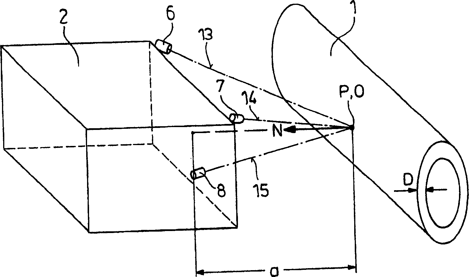
[0021] First, refer to figure 1 To describe the principle of measuring the wall thickness D of the tube 1 by means of the laser-ultrasonic method and using an interferometer, here preferably a Fabry-Pérot interferometer.

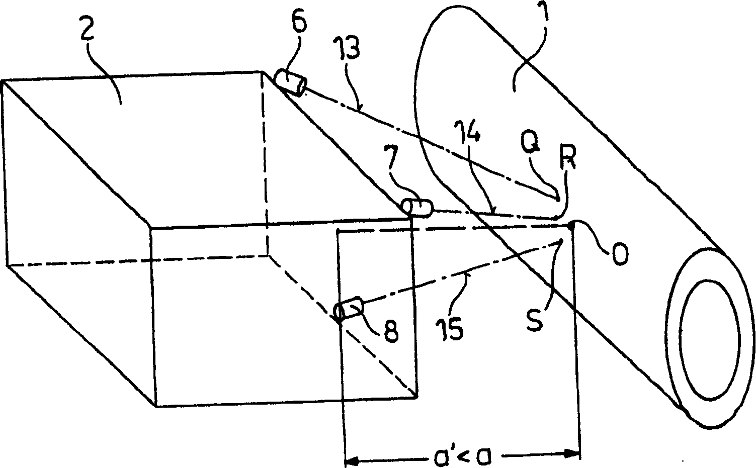
[0022] The wall thickness D of a rolled tube 1 moving in the direction of the arrow should be measured. A laser-ultrasonic wall thickness measuring device based on the typical ultrasonic travel time measurement principle is used. Given the known ultrasonic velocity in the material of the tube 1 , the desired wall thickness D is obtained from the time taken for an ultrasonic pulse to pass through the wall of the tube 1 twice. In thermal wall thickness measurements in the temperature range of approximately 1000 °C, ultrasonic coupling requires a contact-free visual method not only on the excitation side but also on the detection side, where the measuring head 2 of the laser-ultrasonic wall thickness measuring device itself can be connected to the tube 1 Move...


PUM


Abstract

Device for measuring the wall thickness (D) of a pipe (1) in a rolling mill comprises a laser ultrasound measuring unit having a measuring head (2) containing an exciting laser, an illuminating laser and a collecting lens for collecting light scattered from the pipe surface into the head. Lamps (6, 7, 8) emitting a bundled light and fixed to different sites on the head are also included.

Description

technical field [0001] The invention relates to a device for measuring the wall thickness of a tube in a tube rolling mill, which device has a measuring head of a laser ultrasonic measuring device, in which an excitation laser, an irradiating laser and a device for collecting reflections from the tube surface into the measuring head are arranged. Converging optics. Background technique [0002] Steel tubes are used in many technical fields, which can be produced, for example, by processing cylindrical raw material into blank tubes in cross-rolling mills using an axially fixed pierced mandrel. To process cylindrical stock into seamless tubes, the stock is rolled through a mandrel. Such a method is disclosed, for example, in EP 0 940 193 A2. [0003] In the process of tension reducing rolling and reducing and sizing rolling of seamless steel pipes, the pipes to be processed pass through a rolling mill train in which several rolling mill stands are arranged one behind the oth...

Claims


Application Information

Patent Timeline
Patent Type & Authority Patents(China)
IPC IPC(8): G01B17/02G01B11/00B21B37/16G01B11/02G01B11/06
CPCG01B11/026G01B11/0691
Inventor M·绍尔兰德G·-J·德佩
Owner SMS MEER
Learn More