
Rod type lens array

A rod lens and array technology, applied in the field of rod lens array, can solve the problem that the processing speed cannot be fully improved

Inactive Publication Date: 2006-05-03
NIPPON SHEET GLASS CO LTD
View PDF2 Cites 0 Cited by
  • Summary
  • Abstract
  • Description
  • Claims
  • Application Information

AI Technical Summary

Problems solved by technology

Therefore, in the related art, a large load wave is imposed on the light source, or the sensor / light guide, so that the processing speed of the system (such as the reading speed of a scanner or the printing speed of a printer) cannot be sufficiently improved as expected.

Method used


Image

  • Rod type lens array
  • Rod type lens array
  • Rod type lens array

Examples


Embodiment

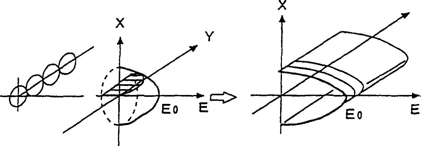
[0039] Figure 4 shows a rod lens array applied in a linear scanning system, with rows 2 to 12 in its transverse direction, and the aperture angle θ 0 In the case of =22.7°, the calculation results of the relationship between the linear scan equivalent F value and the degree of overlap m. The equivalent value F is obtained in this way: "The central illuminance is transformed after obtaining the light intensity distribution of a multi-row array as a superposition of parabolic distributions, where each parabolic distribution is obtained along a single-row array collected in the thickness direction and each considered to be a parabolic distribution consistent in the length direction". By the way, in Figure 4 In the case shown, the opening angle θ 0 is 22.7°. However, even when other values ​​are used for the opening angle, the position (m value) of the intersection of the curves corresponding to the number of rows does not change unless the absolute value of the opening angl...


PUM


Abstract

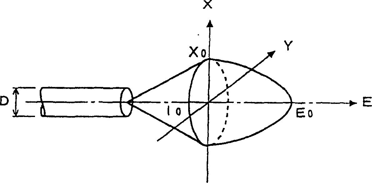
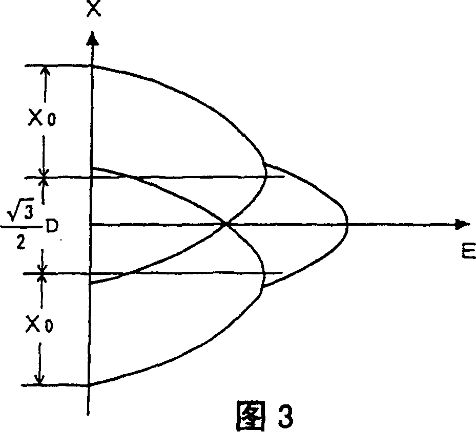
A rod lens array, in which a large number of rod lens elements are combined into one unit, and at the same time, a large number of rod lens elements are arranged in multiple rows, wherein, when m is equal to X 0 / D, where D is the diameter of each lens, X 0 is the radius of the visual threshold generated by each lens, the number N of rows and the overlapping degree m of images satisfy the relationship: {3(N-1)N / 16} 1 / 2 <m≤[N(N+1)・{α(N+2)-(N-1)} / {α(N+1)-N}] 1 / 2 / 4 and 6≤N≤8, α is selected from 0.9, 0.95 and 1.

Description

technical field [0001] The present invention relates to a rod lens array in which a large number of rod lens elements are combined into one unit, and at the same time, a large number of rod lens elements are arrayed in a plurality of rows, and also relates to an image forming apparatus using the rod lens array . More specifically, the present invention relates to a rod lens array in which, as long as attention is paid to the correlation between the number N of lens element rows and the degree of overlap m of images, by defining the relationship between the two, although the number of lens rows is the smallest , the performance (brightness) of the array can also be improved, and an image-forming device uses the rod lens array. It also relates to a method of producing a rod lens array. This technique is applied to an image forming apparatus having a linear scanning type optical system, such as a reading system of a scanner or a writing system of an LED printer. Background te...

Claims


Application Information

Patent Timeline
Patent Type & Authority Patents(China)
IPC IPC(8): G02B3/06G02B3/08H04N1/04B41J2/44B41J2/45B41J2/455G02B3/00G02B6/04G02B6/06H04N1/036
CPCG02B3/005
Inventor 小木秀也
Owner NIPPON SHEET GLASS CO LTD
Learn More