
Method and tool for producing a press joint connection

A connection method and a technology of connectors, which are applied in connection, manufacturing tools, metal processing equipment, etc., can solve problems such as elastic limitations of connection points, and achieve the effect of high working capacity

Inactive Publication Date: 2006-05-24
TOX PRESSOTECHNIK GMBH & CO KG
View PDF2 Cites 1 Cited by
  • Summary
  • Abstract
  • Description
  • Claims
  • Application Information

AI Technical Summary

Problems solved by technology

[0003] The disadvantage of this quick and precise machining of the mating connection is that a die with a dividing wall leads to a limitation of the elasticity of the connection point

Method used


Image

  • Method and tool for producing a press joint connection
  • Method and tool for producing a press joint connection
  • Method and tool for producing a press joint connection

Examples


Embodiment Construction

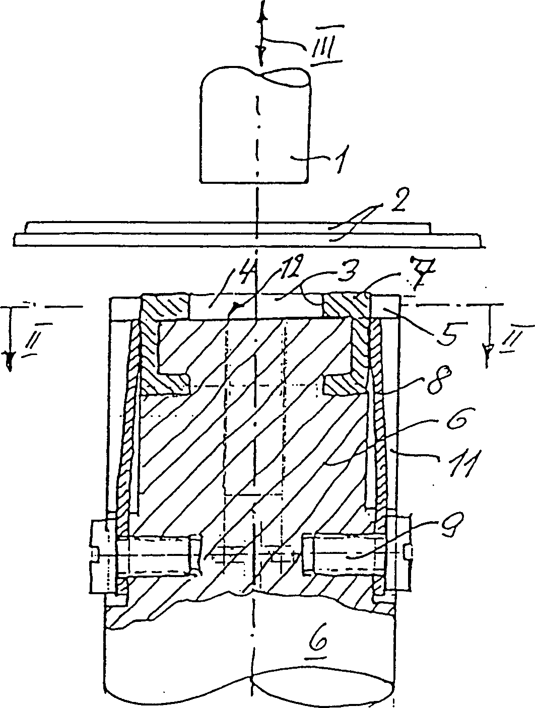
[0026] figure 1 Shown according to the tool of the present invention in the explosion stroke diagram, that is, the punch 1 corresponding to the arrow III can control its working stroke, and can press two mutually overlapping plates 2 into the die 4 in a hole 3. The die is formed by a stationary wall section 5 of the forging die 6 and by a radially outwardly movable bracket 7 which is moved by means of a leaf spring 8 into the starting position shown in the figure. The leaf spring 8 is fixed on the forging die 6 with screws 9 and is arranged in the longitudinal groove 11 of the forging die 6 . Bore 3 is bounded downwards by a base plate 12 formed by die 6 .

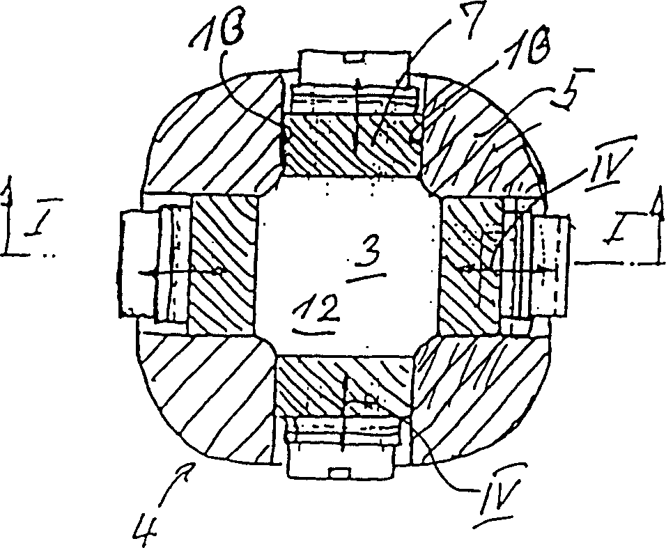
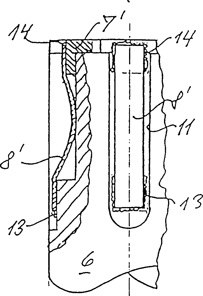
[0027] like figure 2 As shown, the bow 7 between the fixed wall plates 5 of the forging die 6 can be moved axially. The guide wall 13 on the fixed wall section 5 thus serves as a die. During movement, the bracket 7 slides onto the bottom 12 of the blind hole 3 . During the displacement, the bracket 7 moves correspon...


PUM


Abstract

A method and tool for producing a press joint connection, in which portions of the radial lateral walls of an opening of a die are configured as flexible displaceable segments, whereas other sections, when viewed from a periphery of the opening, remain rigidly connected to the die.

Description

technical field [0001] The invention relates to a method for connecting components, for example in the case of plates, bolts, nuts or the like, to a plate forming a through-joint connection, and also to a tool for this method. Background technique [0002] In a method of known type (DE-OS3532900), a plate is extruded in the die hole, the material of which is pressed radially outwards from the bottom surface onto the axial wall of the die hole, while these are extruded The material is clamped behind by means of the through-holes of the die work, and thus forms a firm connection between the part and the plate. This type of connection is often referred to as a mating connection. It could conceivably be used to join two or more plates that overlap each other, or also bolts or similar on one or more plates. At the same time, the so-called punches used therein are either made of soft, deformable material with sufficient hardness to carry out a press-in process with the sheet met...

Claims


Application Information

Patent Timeline
Patent Type & Authority Patents(China)
IPC IPC(8): B21D39/03B21J13/02
CPCB21D39/031B21D39/035Y10T29/49968Y10T403/4966Y10T29/49936Y10T29/49908Y10T29/53709Y10T29/49938Y10T29/49963Y10T83/546B21D39/03
Inventor 尤金·亚布
Owner TOX PRESSOTECHNIK GMBH & CO KG
Learn More