
Reactor with anaerobic suspension bed

A reactor and suspended bed technology, applied in the field of anaerobic bioreactors, can solve the problems of slow start-up, high operating costs, and easy acidification of anaerobic reactors, so as to improve impact resistance and operational stability, and shorten the start-up period , the effect of high operating load

Inactive Publication Date: 2006-06-07
TSINGHUA UNIV
View PDF0 Cites 0 Cited by
  • Summary
  • Abstract
  • Description
  • Claims
  • Application Information

AI Technical Summary

Problems solved by technology

[0005] The purpose of the present invention is to solve the problems of slow start-up, easy acidification and high operating cost of existing anaerobic reactors

Method used


Image

  • Reactor with anaerobic suspension bed
  • Reactor with anaerobic suspension bed
  • Reactor with anaerobic suspension bed

Examples


Embodiment Construction

[0014] Various embodiments of the present invention and their working process will be further described below in conjunction with the accompanying drawings.

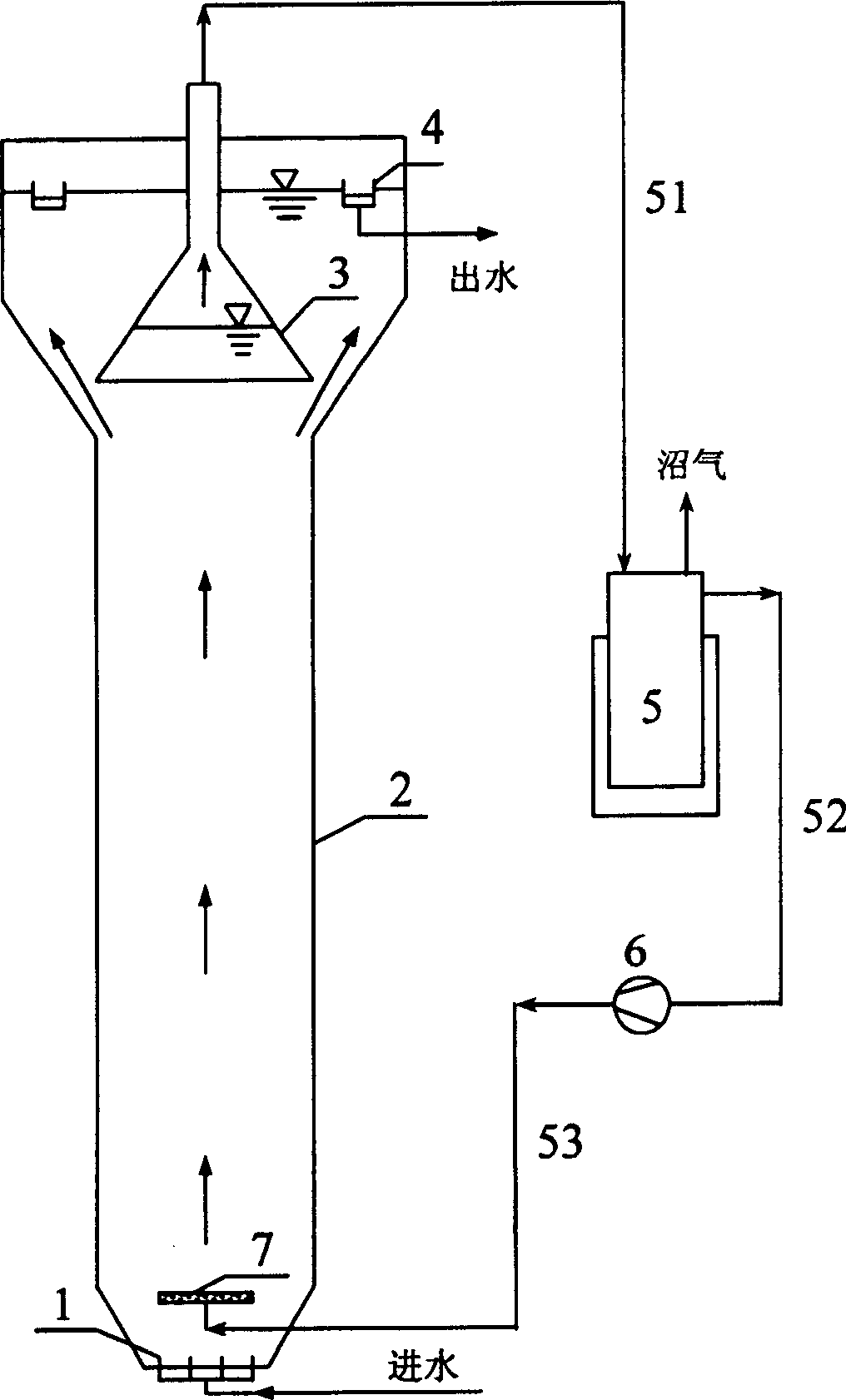
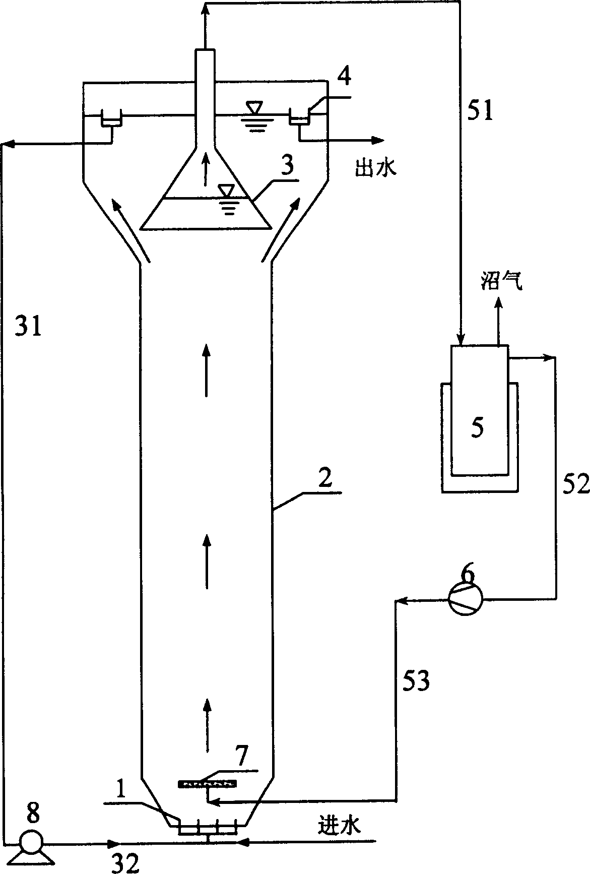
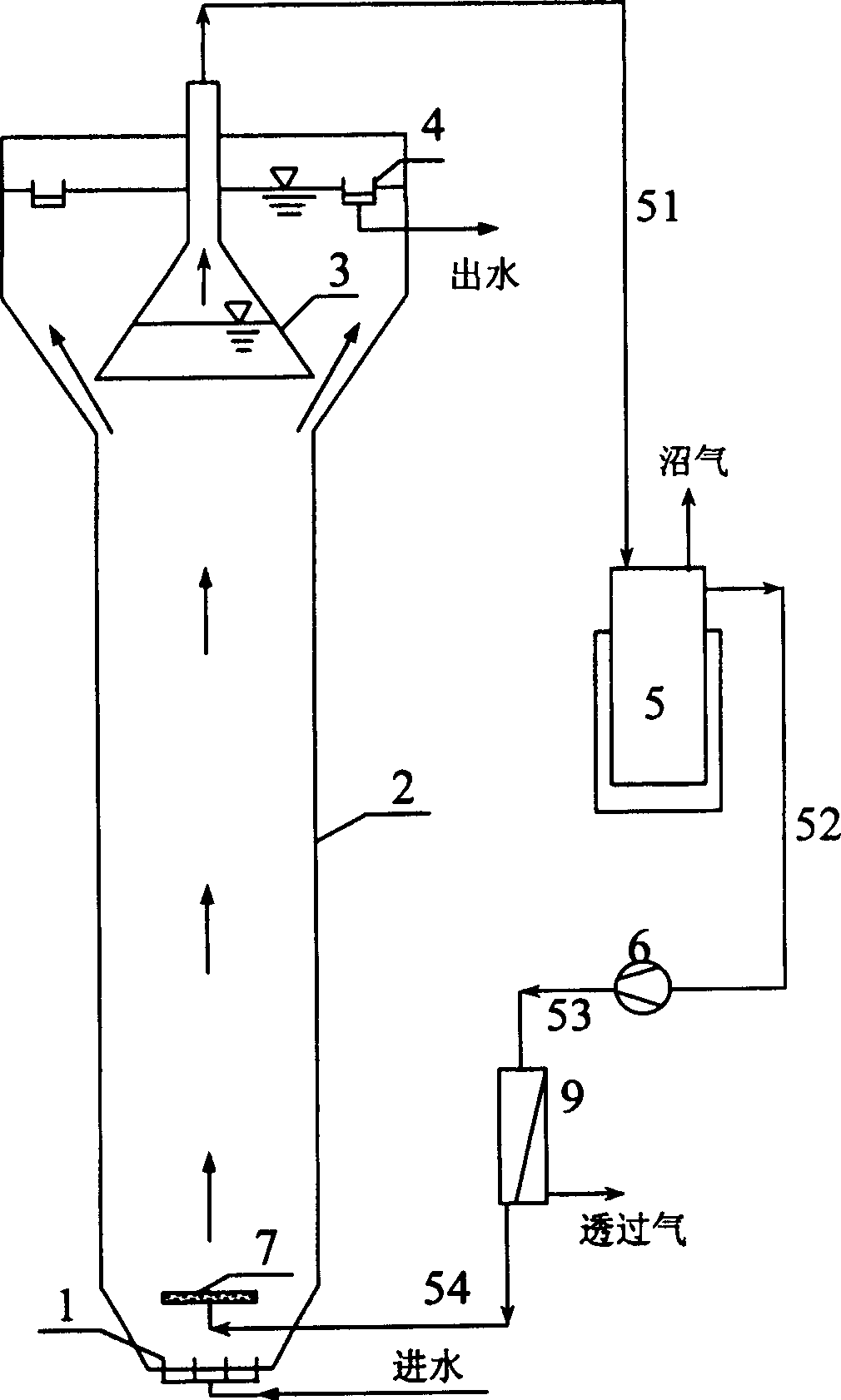
[0015] Such as figure 1 As shown, the reactor described in the first embodiment of the present invention includes a biological reaction unit and a biogas circulation unit, wherein the biological reaction unit includes a water distributor 1, a biological reaction tower 2, a three-phase separator 3 and an outlet weir 4, and the biogas The circulation unit includes a biogas buffer cabinet 5 , an air pump 6 and an air distributor 7 .

[0016] The water distributor 1 and the air distributor 7 are all arranged at the bottom of the biological reaction tower 2, the air distributor 7 is arranged above the water distributor 1, the three-phase separator 3 is arranged on the top of the biological reaction tower 2, and the water outlet weir 4 is arranged on the top of biological reaction tower 2. The three-phase separator 3 is conn...


PUM


Abstract

An anaerobic suspension-bed reactor for biologically treating sewage is composed of a biologic reaction unit whose main component is a biologic reaction tower with water distributor and three-phase separator, and a marsh gas circulation unit consisting of march gas buffering cabin, pneumatic pump and gas distributor.

Description

technical field [0001] The invention relates to an anaerobic biological treatment equipment for organic waste water, in particular to an anaerobic biological reactor for biogas circulation and effluent backflow. Background technique [0002] The anaerobic expansion or fluidized bed reactors currently used in the prior art use effluent backflow to increase the hydraulic rising flow rate in the reactor, so that the granular sludge is in an expanded or fluidized state in the reaction zone. Most of the organic matter in the wastewater is removed when it flows through the granular sludge bed area, and converted into methane and carbon dioxide. The upper part of the reactor is equipped with a three-phase separator, and the effluent is discharged after gas-liquid separation and precipitation, and the biogas is also discharged after collection. . The effluent backflow promotes the expansion or fluidization of the granular sludge bed: ① It can reduce the blockage of the bed and avoi...

Claims


Application Information

Patent Timeline
Patent Type & Authority Patents(China)
IPC IPC(8): C02F3/28C02F11/04
CPCY02E50/30Y02W10/20
Inventor 左剑恶李建平杨洋张文
Owner TSINGHUA UNIV
Learn More