Multiple mode direct conversion receiver

A technology for receivers and communication receivers, applied in discontinuous tuning of frequency band selection, frequency division multiplexing system components, electrical components, etc., can solve problems such as difficulty in obtaining multi-mode functions

Inactive Publication Date: 2000-08-02
TELEFON AB LM ERICSSON (PUBL)
View PDF0 Cites 18 Cited by
  • Summary
  • Abstract
  • Description
  • Claims
  • Application Information

AI Technical Summary

Problems solved by technology

Since superheterodyne receivers use multiple frequencies to process signals, it is difficult to achieve multimode capability without a lot of duplicative hardware in the receiver

Method used


Image

  • Multiple mode direct conversion receiver
  • Multiple mode direct conversion receiver
  • Multiple mode direct conversion receiver

Examples


Embodiment Construction

[0015] DETAILED DESCRIPTION OF THE PREFERRED EMBODIMENT

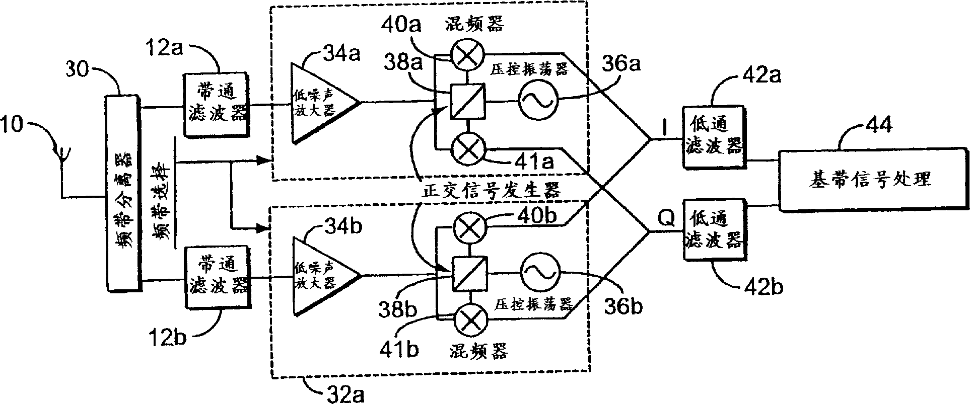
[0016] figure 2 is a block diagram of the first preferred embodiment of the direct conversion receiver of the present invention. This receiver has an antenna 10 for receiving signals, and a frequency band separator 30 for separating signals of first and second frequency bands from the received signals. First and second bandpass filters 12a and 12b filter signals in first and second frequency bands, respectively. These bandpass filters are all frequency (band) specific, and they can be omitted if the linearity of the receiver is good. Alternatively, the band splitter 30 can be omitted if a band pass filter is used. In most cases, a bandpass filter is required to reduce power consumption. Alternatively, a multiband filter having one input and multiple outputs (one output for each frequency band) may replace band splitter 30 and bandpass filters 12a and 12b. The signals output by the filters 12a and 12b are sent to th...


PUM


Abstract

A multiple-mode receiver incorporating direct conversion (processing received signals using intermediate frequencies within the same frequency range as the received signal bandwidth) rather than superheterodyne circuitry, allowing receiver hardware components to be re-used rather than replicated for each band. Various embodiments are disclosed in which low pass filters, mixers, quadrature generators, oscillators, and amplifiers are re-used.

Description

field of invention [0001] The present invention relates generally to multi-band wireless communication devices and systems. More particularly, the present invention relates to multiband wireless communication devices and systems that employ direct conversion rather than superheterodyne circuits. Background of the invention [0002] As the field of wireless communication continues to develop rapidly, the ever-increasing number of systems and frequency bands used conflicts with user requirements for mobility. That is, problems arise when different consumers join wireless communication systems with different technical standards. To avoid this problem, a global standard system has emerged in which all wireless communication systems use the same frequency band. However, this solution is not realistic because operators of wireless communication systems want to maximize the return on the many different existing systems they have invested in or systems under construction. In addi...

Claims


Application Information

Patent Timeline
Patent Type & Authority Applications(China)
IPC IPC(8): H04L27/22H03J5/24H04B1/16H04B1/30H04B1/40H04J1/04H04W88/06
CPCH04B1/0057H03J5/244H04W88/06H04B1/006H04B1/005H04B1/406H04B1/16
Inventor M·伊斯贝里B·林德奎斯特P·雅科布松J·塞兰德K·古斯塔夫松L·P·昆克尔T·卡尔松J·曼纳斯塔勒
Owner TELEFON AB LM ERICSSON (PUBL)
Why Eureka
Try Eureka