
Gas supply device

一种供气装置、供气通道的技术,应用在电气元件、气态化学镀覆、涂层等方向,能够解决不能实现均匀而最优地喷射、难以调整基板喷射位置或喷射角度等问题

Inactive Publication Date: 2006-07-05
SAMSUNG ELECTRONICS CO LTD
View PDF1 Cites 0 Cited by
  • Summary
  • Abstract
  • Description
  • Claims
  • Application Information

AI Technical Summary

Problems solved by technology

Therefore, it is difficult to adjust the spraying position or spraying angle for various substrates, causing a problem that uniform and optimal spraying onto these substrates cannot be achieved.

Method used


Image

  • Gas supply device
  • Gas supply device
  • Gas supply device

Examples


Embodiment Construction

[0037] Hereinafter, embodiments of the present invention will be described in detail with reference to the accompanying drawings, in which the same reference numerals refer to the same elements throughout. However, the present invention may be embodied in many different forms and should not be construed as being limited to the embodiments set forth herein. On the contrary, these embodiments are arranged so that this disclosure will be detailed and comprehensive, and will fully convey the principles of the present invention to those skilled in the art.

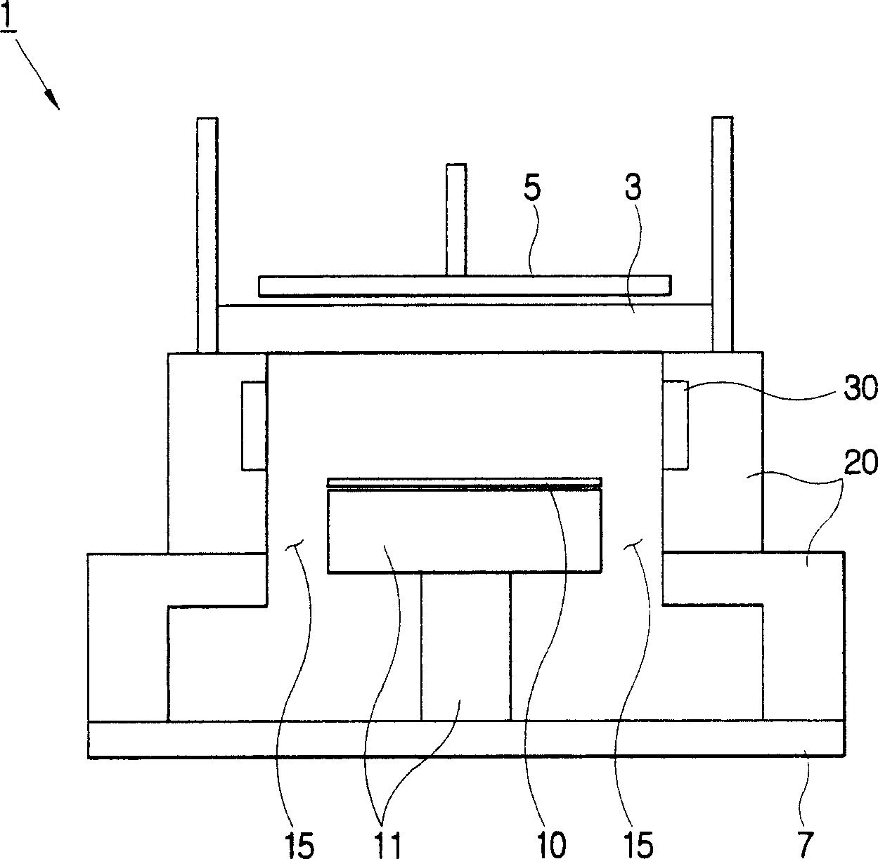
[0038] figure 1 It is a cross-sectional view of the chamber 1 provided with the air supply device 20 according to the first embodiment of the present invention. Such as figure 1 As shown, the chamber 1 includes a base 7; an annular air supply device 20 assembled on the base 7; a substrate holder 11, which is arranged in the middle of the air supply device 20, to hold a substrate 10, the substrate 10 Is the wafer; the plasma ante...


PUM


Abstract

A gas supplying apparatus for supplying deposition gas onto a substrate surface, the gas supplying apparatus comprising: a gas supplying ring with one or more gas supplying channels formed along the interior of the gas supplying ring and with a plurality of gas distribution channels directed toward a center of the gas supplying ring; and a plurality of adapters with gas nozzles connecting to the gas distribution channels, respectively, that detachably connect to the interior of the gas supplying ring, wherein the gas nozzles have a variety of injection configurations.

Description

Technical field [0001] The present invention relates to a gas supply device, and more particularly, to a gas supply device for supplying deposition gas to the surface of a substrate located in a chamber. Background technique [0002] The gas supply device is used to supply the gas to be deposited to the surface of a substrate, such as a wafer located in a chamber in a semiconductor manufacturing process. Generally speaking, the gas supply device is required to evenly distribute the gas on the surface of the substrate. [0003] A conventional gas supply device is disclosed in US Patent No. 6,143,078, detailing the gas supply device in the CVD (chemical vapor deposition) manufacturing process. Such as Picture 12 As shown, the gas supply device for depositing a thin film on a substrate includes a plurality of orifices arranged in a gas distribution ring 410 in a processing chamber, and a plurality of first gas injections are arranged in some orifices for injecting a first gas into ...

Claims


Application Information

Patent Timeline
Patent Type & Authority Patents(China)
IPC IPC(8): H01L21/00H01L21/205C23C16/00H05H1/46C23C16/44C23C16/455H01L21/02
CPCC23C16/4558H01L21/02C23C16/45563C23C16/45574
Inventor 韩奎熙刘尚昱李锡燀
Owner SAMSUNG ELECTRONICS CO LTD
Features
  • Generate Ideas
  • Intellectual Property
  • Life Sciences
  • Materials
  • Tech Scout
  • Unparalleled Data Quality
  • Higher Quality Content
  • 60% Fewer Hallucinations
Learn More