Foundry rolling unit

A kind of equipment, casting and rolling technology, applied in metal rolling and other directions, can solve the problems of low casting speed, difficult casting, affecting strip quality, etc., and achieve the effect of large production flow

Inactive Publication Date: 2006-08-09
PRIMETALS TECH GERMANY
View PDF2 Cites 0 Cited by
  • Summary
  • Abstract
  • Description
  • Claims
  • Application Information

AI Technical Summary

Problems solved by technology

However, it will bring some difficulties in casting when producing stainless steel and high alloy steel
e.g. relatively low casting speed due to boiling of molten steel during casting
In addition, when changing frequently between stainless steel, high alloy steel and carbon steel, it may also cause problems in the operation of the finishing mill train and thus affect the quality of the processed strip

Method used


Image

  • Foundry rolling unit
  • Foundry rolling unit

Examples


Embodiment Construction

[0019] An embodiment of the invention is described in detail below with reference to the drawings.

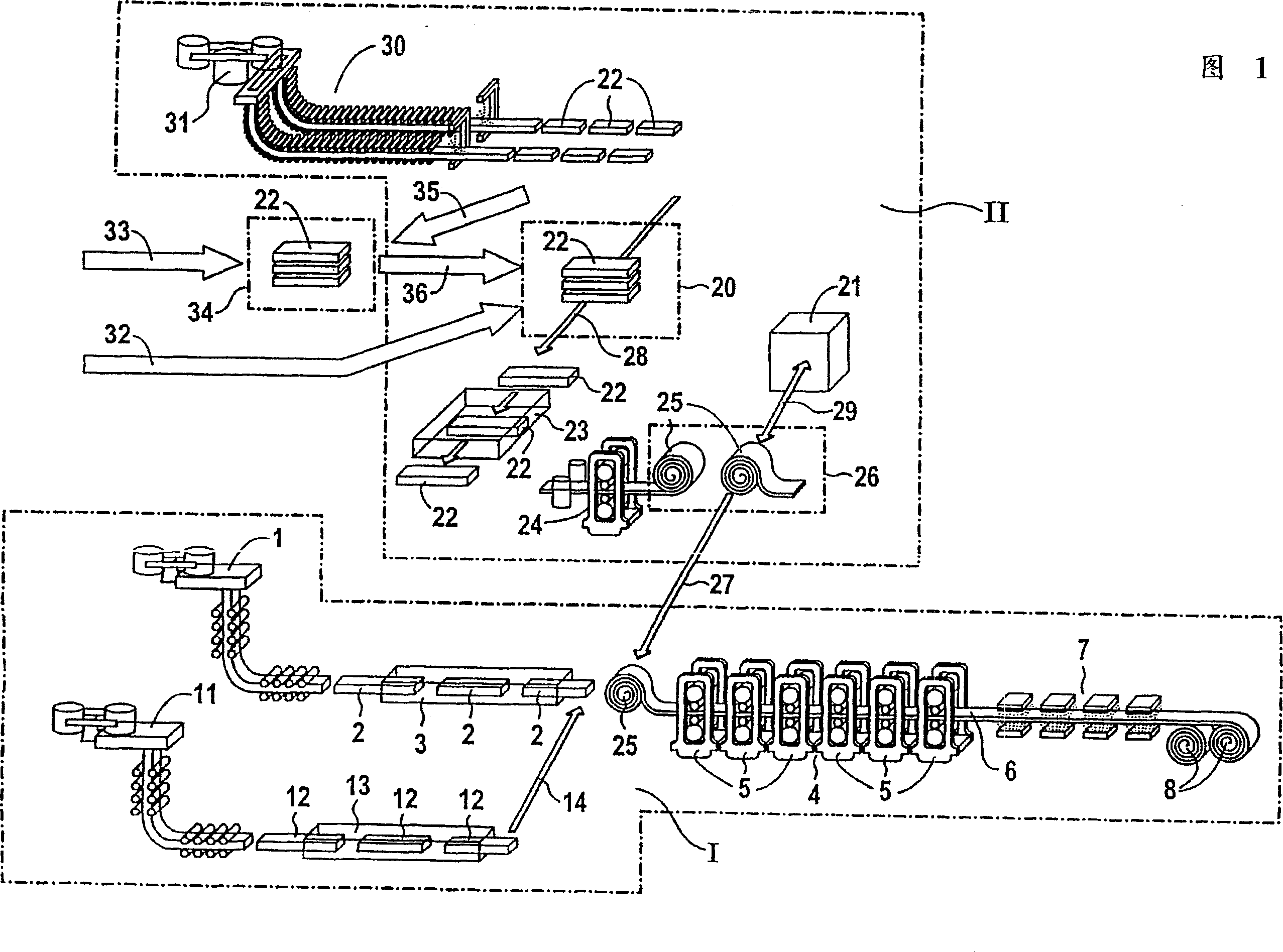
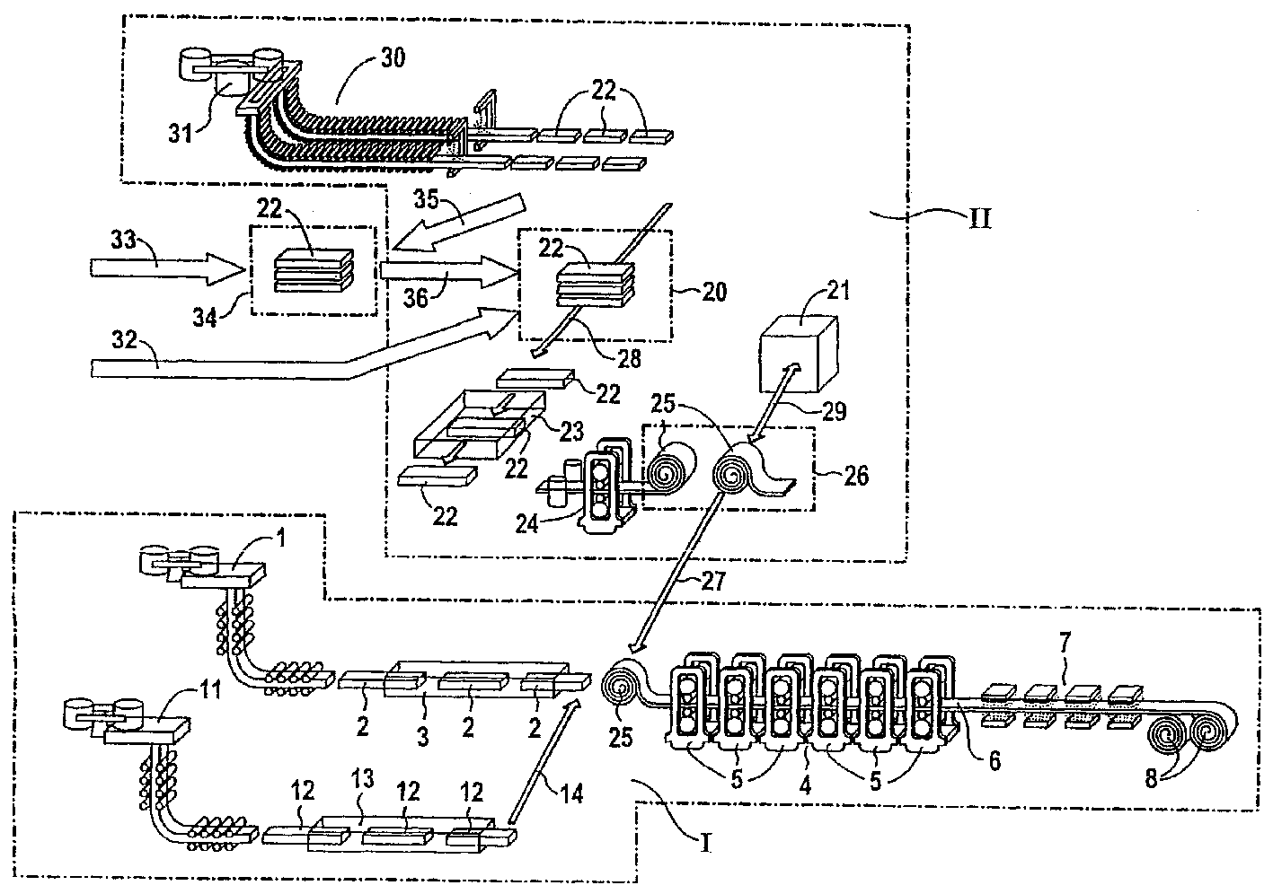
[0020] The first production line is denoted by I in the drawings. The first production line I comprises a casting machine 1 in which thin slabs 2 are cast. These thin slabs 2 are conveyed to a tunnel furnace 3 . The tunnel furnace 3 leads to a finishing train 4 which has six rolling stands 5 in the illustrated embodiment. In the finishing train 4 the thin slab 2 is rolled to form a hot strip 6 . After leaving the finishing train 4 , the rolled hot strip 6 is conveyed to a cooling section 7 and coiled on a coiler 8 .

[0021] As a first extension to the embodiment of the cast-rolling plant shown in the figures, a further casting machine 11 is provided on the first production line I. The casting machine 11 is connected in parallel with the casting machine 1 in the process flow. The casting machine 11 likewise produces thin slabs 12 . The thin slabs 2 are conveyed to a tunne...


PUM


Abstract

The invention relates to a foundry rolling unit, comprising a first production line (I), with at least one casting machine (1, 11), the thin slabs (2, 12) of which may be introduced into at least one tunnel furnace (3, 13), whereby said tunnel furnace (3, 13) opens out into at least one finishing train (4), with at least one mill stand (5). After leaving the finishing train (4) the rolled hot strips may be introduced into at least one cooling run (7) and may be rolled on at least one coiler (8). The foundry rolling unit furthermore comprises a second production line (II) arranged in an at least partly parallel manner in terms of production, with at least one slab introducing device (20), through which the slabs (22) may be introduced into at least one reheating oven (23) and at least one cogging stand (24) arranged thereafter. The rolled pre-strips may be obtained as coils (25) from at least one coil-box (26). The foundry rolling unit further comprises a coil transport device (27), by means of which the coils (25) may be transferred before the finishing train (4), from the second production line (II) to the first production line (I). The coils (25) may be removed from the coil box (26) and transported to the input of the finishing train (4), in order to carry out introduction of the pre-strips. By means of the above it is possible to produce a complete spectrum of different steel types, in particular stainless steel and high-alloyed steel, whilst achieving a corresponding high throughput.

Description

technical field [0001] The invention relates to a casting and rolling equipment. Background technique [0002] For example, thin slabs (with a thickness of 40 to 90 mm) are processed in such casting and rolling plants to form strips. The plant includes a casting machine, from which thin slabs can be fed to at least one tunnel furnace. The tunnel furnace leads to a finishing train having at least one rolling stand. The thin slab is rolled into hot strip in the finishing train. After leaving the finishing train, the rolled hot strip is conveyed to at least one cooling section and coiled on at least one coiler. [0003] For example, German patent DE 195 29 049 discloses a high-speed thin-slab plant for producing hot-rolled steel strip from strip-shaped precast material in successive operations. In this, the solidified preformed material is cut into rough strip lengths by means of a continuous slitting plant and brought to rolling temperature in a balancing furnace (Ausgleic...

Claims


Application Information

Patent Timeline
Patent Type & Authority Patents(China)
IPC IPC(8): B21B1/46B21B1/00B22D11/12B22D11/14
CPCB21B1/466Y10T29/5184
Inventor 托马斯·普科弗里德曼·施密德尤维·斯特默
Owner PRIMETALS TECH GERMANY
Why Eureka
Try Eureka