Supercharge Your Innovation With Domain-Expert AI Agents!

Photomultiplier

A photomultiplier tube and photoelectric technology, which is applied in the direction of dynode, electron multiplier details, electrode devices with multiple dynodes, etc., can solve the problems of dynode sloshing, easy loosening, deformation, etc.

Inactive Publication Date: 2006-08-09
HAMAMATSU PHOTONICS KK
View PDF4 Cites 0 Cited by
  • Summary
  • Abstract
  • Description
  • Claims
  • Application Information

AI Technical Summary

Problems solved by technology

[0006] However, in the configuration in which both ends of each dynode are supported by a single support part, looseness easily occurs in the rotation direction around the support part.
In this way, when the dynode operates, it will affect the output signal
[0007] In addition, in the case of the photomultiplier tube described in JP-A-9-180670, when there is a gap due to the margin for insertion into the respective holes, the plate-shaped concave plate and the upper plate will be separated when subjected to severe vibration. The side and lower support parts are deformed, and the dynode is greatly swayed in the hole, so it cannot be fixed reliably
[0008] In addition, for the photomultiplier tubes described in JP-A-60-262340, JP-A-60-254547, and JP-A-60-254548, when there is a gap due to the margin inserted into the respective slits, The dynode has a large slosh in the longitudinal direction of the slit and cannot be fixed reliably

Method used


Image

  • Photomultiplier
  • Photomultiplier
  • Photomultiplier

Examples


Embodiment Construction

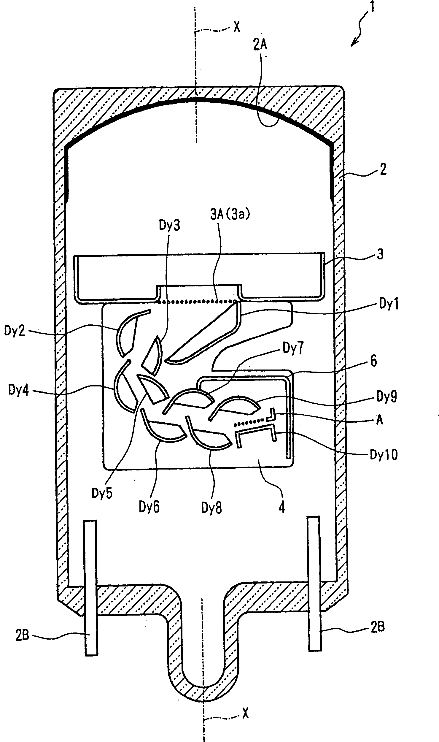
[0026] according to Figure 1-Figure 6 A photomultiplier tube according to an embodiment of the present invention will be described. The photomultiplier tube 1 of this embodiment includes a single tubular vacuum container 2 having a tube axis X. As shown in FIG. figure 1 It is a cross-sectional view showing a state where the photomultiplier tube 1 is cut along the tube axis X. FIG. The tubular vacuum vessel 2 is made of a material such as Kovar (cobalt) glass, for example.

[0027] Both ends of the tubular vacuum container 2 in the direction of the tube axis X are sealed, and one end is planar, and a photoelectric surface 2A that emits electrons upon receiving light is formed on the inner surface. The photoelectric surface 2A is formed, for example, by reacting alkali metal vapor on antimony deposited in advance on the inner surface of one end of the tubular vacuum container 2 . In addition, a plurality of conductive pins 2B are provided at the other end of the tubular vacu...


PUM


Abstract

A photomultiplier with less rattling between the dynodes and the base, fixed securely and excellent in vibration resistance. The dynode (Dy2) of the second stage has a curved surface part (Dy2A) having a generally arcuate cross section and a flat surface part (Dy2B) continuous and in flash with the curved surface both forming a secondary electron surface. At the ends of the curved surface (Dy2A) in the longitudinal direction, side parts (Dy2C, Dy2C) rising from the curved surface part (Dy2A) are formed by press. First (Dy2D) lugs project outward from the side parts (Dy2). At the ends of the flat surface part (Dy2B) in the longitudinal direction, second lugs (Dy2E) project outward similarly. The second lugs (Dy2E) are not parallel to the first lugs (Dy2D) and they form a predetermined angle.

Description

technical field [0001] The present invention relates to a photomultiplier tube, in particular to a photomultiplier tube excellent in vibration resistance. Background technique [0002] For high-vibration-resistant photomultiplier tubes for the purpose of oil exploration, since accurate operation is required for deep underground excavation, disturbance during vibration and time-dependent changes become problems. [0003] In the past, in the case of inserting multi-level dynodes between two ceramic substrates and supporting them to form electron multiplier parts, it is known that a single support part is formed at both ends of each dynode, and each Corresponding single linear slits are also formed on the ceramic substrate, and the supporting parts are inserted into the corresponding slits for support. [0004] In addition, in the photomultiplier tube described in JP-A-9-180670, two support portions are protrudingly provided at both end portions of the ...

Claims


Application Information

Patent Timeline
Patent Type & Authority Patents(China)
IPC IPC(8): H01J43/20
CPCH01J43/20
Inventor 石津智洋藤田哲也
Owner HAMAMATSU PHOTONICS KK
Features
  • R&D
  • Intellectual Property
  • Life Sciences
  • Materials
  • Tech Scout
  • Unparalleled Data Quality
  • Higher Quality Content
  • 60% Fewer Hallucinations
Learn More