High-power pulsed magnetron sputtering

a pulsed magnetron and sputtering technology, applied in the direction of electrolysis components, vacuum evaporation coatings, coatings, etc., can solve the problems of relatively low uniformity of films, relatively complex and expensive systems to implement, and the target utilization rate of conventional magnetron sputtering systems is also relatively poor

Inactive Publication Date: 2006-12-12
ZOND CORP +1
View PDF25 Cites 50 Cited by
  • Summary
  • Abstract
  • Description
  • Claims
  • Application Information

AI Technical Summary

Problems solved by technology

Conventional magnetron sputtering systems deposit films that have relatively low uniformity.
However, the film uniformity can be increased by mechanically moving the substrate and/or the magnetron, but such systems are rel

Method used


Image

  • High-power pulsed magnetron sputtering
  • High-power pulsed magnetron sputtering
  • High-power pulsed magnetron sputtering

Examples


Embodiment Construction

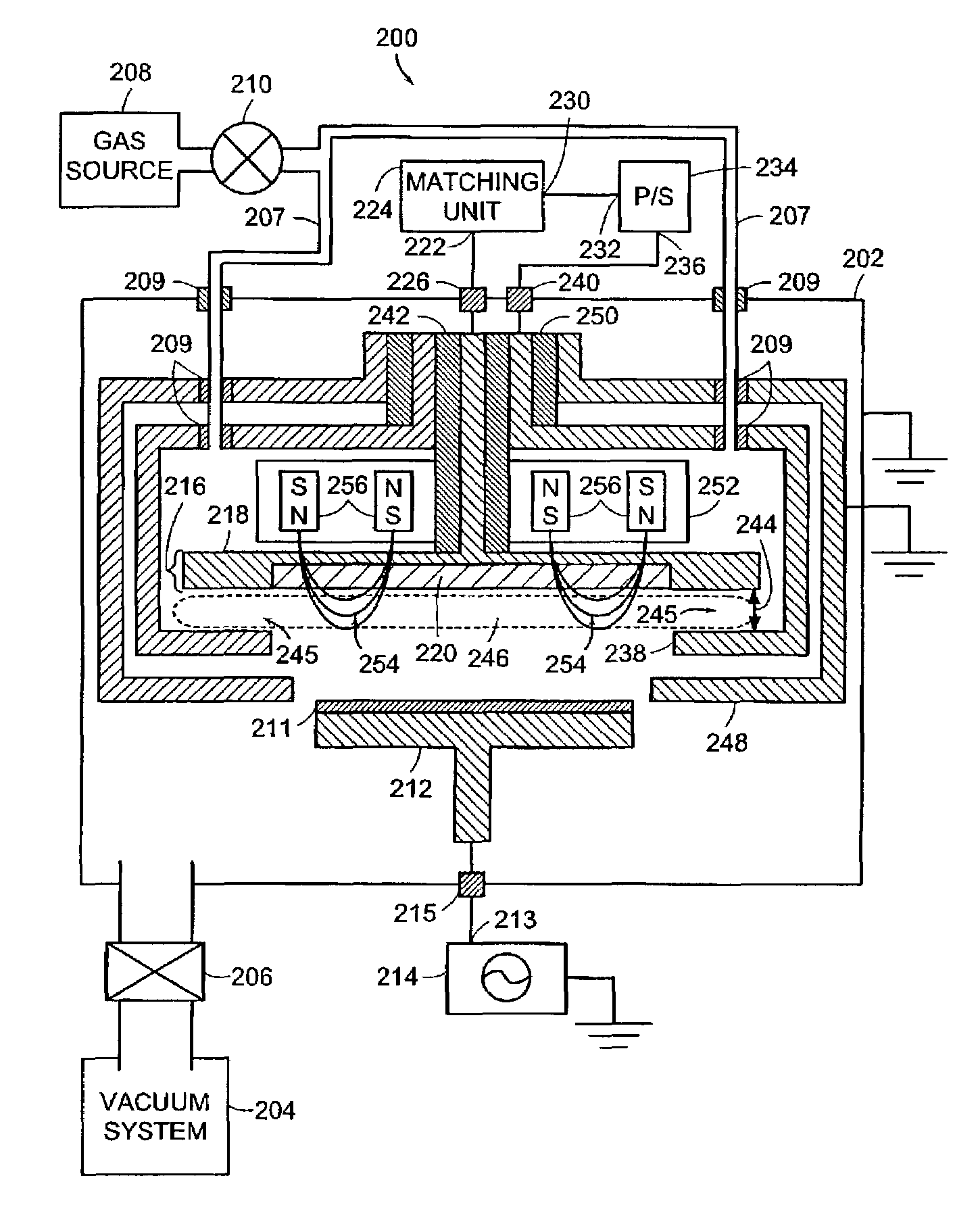
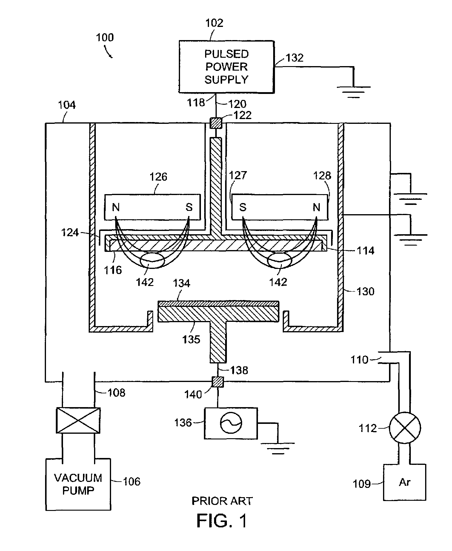
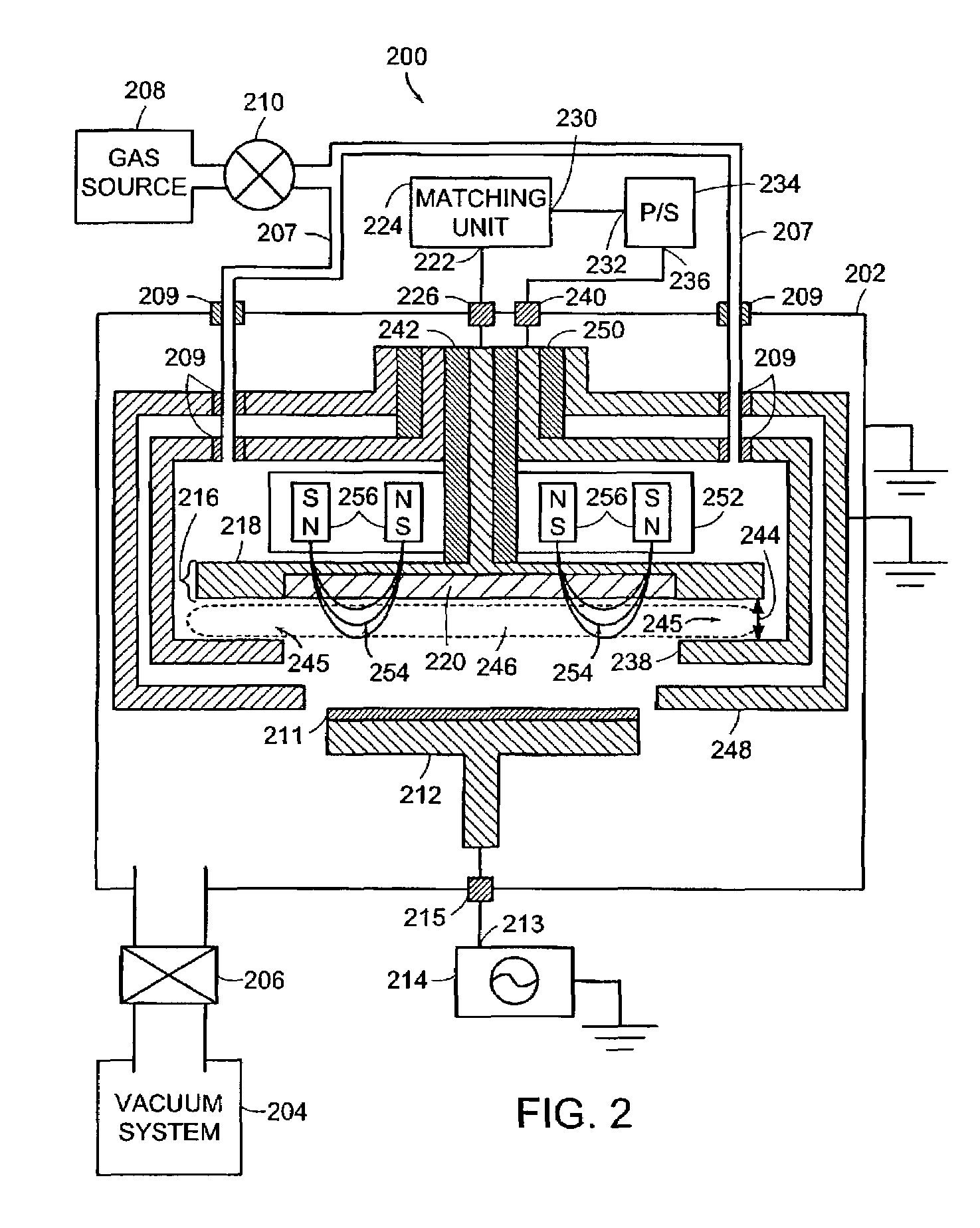
[0021]The magnetic and electric fields in magnetron sputtering systems are concentrated in narrow regions close to the surface of the target. These narrow regions are located between the poles of the magnets used for producing the magnetic field. Most of the ionization of the sputtering gas occurs in these localized regions. The location of the ionization regions causes a non-uniform erosion or wear of the target that results in poor target utilization.

[0022]Increasing the power applied between the target and the anode can increase the amount of ionized gas and, therefore, increase the target utilization. However, undesirable target heating and target damage can occur. Furthermore, increasing the voltage applied between the target and the anode increases the probability of establishing an undesirable electrical discharge (an electrical arc) in the process chamber.

[0023]Pulsing the power applied to the plasma can be advantageous since the average discharge power can remain low while ...


PUM

PropertyMeasurementUnit
Timeaaaaaaaaaa
Timeaaaaaaaaaa
Electric potential / voltageaaaaaaaaaa

Abstract

Magnetically enhanced sputtering methods and apparatus are described. A magnetically enhanced sputtering source according to the present invention includes an anode and a cathode assembly having a target that is positioned adjacent to the anode. An ionization source generates a weakly-ionized plasma proximate to the anode and the cathode assembly. A magnet is positioned to generate a magnetic field proximate to the weakly-ionized plasma. The magnetic field substantially traps electrons in the weakly-ionized plasma proximate to the sputtering target. A power supply produces an electric field in a gap between the anode and the cathode assembly. The electric field generates excited atoms in the weakly ionized plasma and generates secondary electrons from the sputtering target. The secondary electrons ionize the excited atoms, thereby creating a strongly-ionized plasma having ions that impact a surface of the sputtering target to generate sputtering flux.

Description

BACKGROUND OF INVENTION[0001]Sputtering is a well-known technique for depositing films on substrates. Sputtering is the physical ejection of atoms from a target surface and is sometimes referred to as physical vapor deposition (PVD). Ions, such as argon ions, are generated and then directed to a target surface where the ions physically sputter target material atoms. The target material atoms ballistically flow to a substrate where they deposit as a film of target material.[0002]Diode sputtering systems include a target and an anode. Sputtering is achieved in a diode sputtering system by establishing an electrical discharge in a gas between two parallel-plate electrodes inside a chamber. A potential of several kilovolts is typically applied between planar electrodes in an inert gas atmosphere (e.g., argon) at pressures that are between about 10−1 and 10−2 Torr. A plasma discharge is then formed. The plasma discharge is separated from each electrode by what is referred to as the dark ...

Claims


Application Information

Patent Timeline
IPC IPC(8): C23C14/35H01J37/32H01J37/34
CPCC23C14/35H01J37/32082H01J37/3408
Inventor CHISTYAKOV, ROMAN
Owner ZOND CORP
Why Eureka
Try Eureka