Charged particle guide

a technology of charged particles and guide rods, applied in the field of charged particle guides, can solve the problems of increasing the difficulty of endpointing, increasing the difficulty of collection, and affecting the efficiency of secondary electron collection and its attendant image improvement, so as to enhance the generation of end pointing trace, reduce wear, and enhance image generation

Active Publication Date: 2006-11-14
DCG SYST
View PDF7 Cites 50 Cited by
  • Summary
  • Abstract
  • Description
  • Claims
  • Application Information

AI Technical Summary

Benefits of technology

[0014]The bias voltage applied to the charged particle guide, each member, the charged particle detector and other components of the charged particle tool also impact the collecting electric field. Thus, variations in application of the bias voltage are possible. In one aspect, a first voltage is applied to the secondary electron detector housing to define a first collecting electric field and a second voltage is applied to the charged particle guide to define a second collecting electric field. The charged particle guide bias voltage may be less or greater than the charged particle detector housing bias voltage. To collect negatively charged particles, the first and the second voltages are positive to create a first positive collecting electrical field and a second positive collecting electrical field to attract secondary electrons emitted from a sample on the platform upon application of the charged particle beam thereto. Due to the presence of the charged particle guide, secondary electrons are attracted to the scintillator disc, but are not concentrated in a discrete location thereon, which helps to reduce wear.
[0015]In the case of a focused ion beam tool or other charged particle type tool used in IC testing, the first and the second elongate members are arranged proximate the platform to enhance generation of an end pointing trace. The first and the second elongate members may also be arranged proximate the platform to enhance image generation during a circuit editing procedure.

Problems solved by technology

Oftentimes, a large portion of the secondary electrons are emitted away from the SED, making collection difficult.
Thus, endpointing becomes more difficult as the secondary electron emission decreases.
However, in FIB systems where it is difficult or impossible to introduce such an collection field proximate the sample, improving secondary electron collection efficiency and its attendant image improvements remains a problem.
Over time, a “burn” spot will result with much or all of the phosphor burned from the scintillator disc, leading to reduced detection and a reduced lifetime of the disc.

Method used


Image

  • Charged particle guide
  • Charged particle guide
  • Charged particle guide

Examples


Embodiment Construction

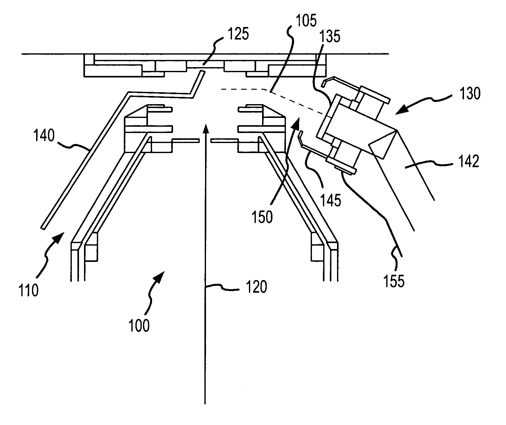
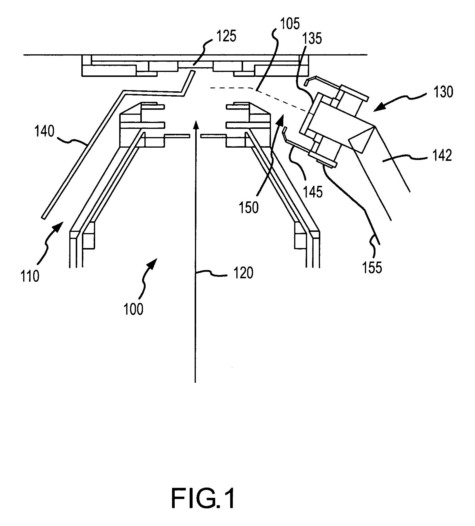
[0038]One aspect of the present invention involves a charged particle guide that attracts and directs charged particles toward a charged particle detector, such as a scintillator disk of a secondary electron detector, and thereby improves its collection efficiency. The charged particle guide includes a plurality of members extending from the charged particle detector toward a sample. A bias voltage, or range of voltages, is applied to the members to introduce an electric field proximate the sample. When employed in a tool that generates a charged particle beam and directs the beam onto the sample, the electric field attracts charged particles emitted from the sample and directs the charged particles to the charged particle detector.

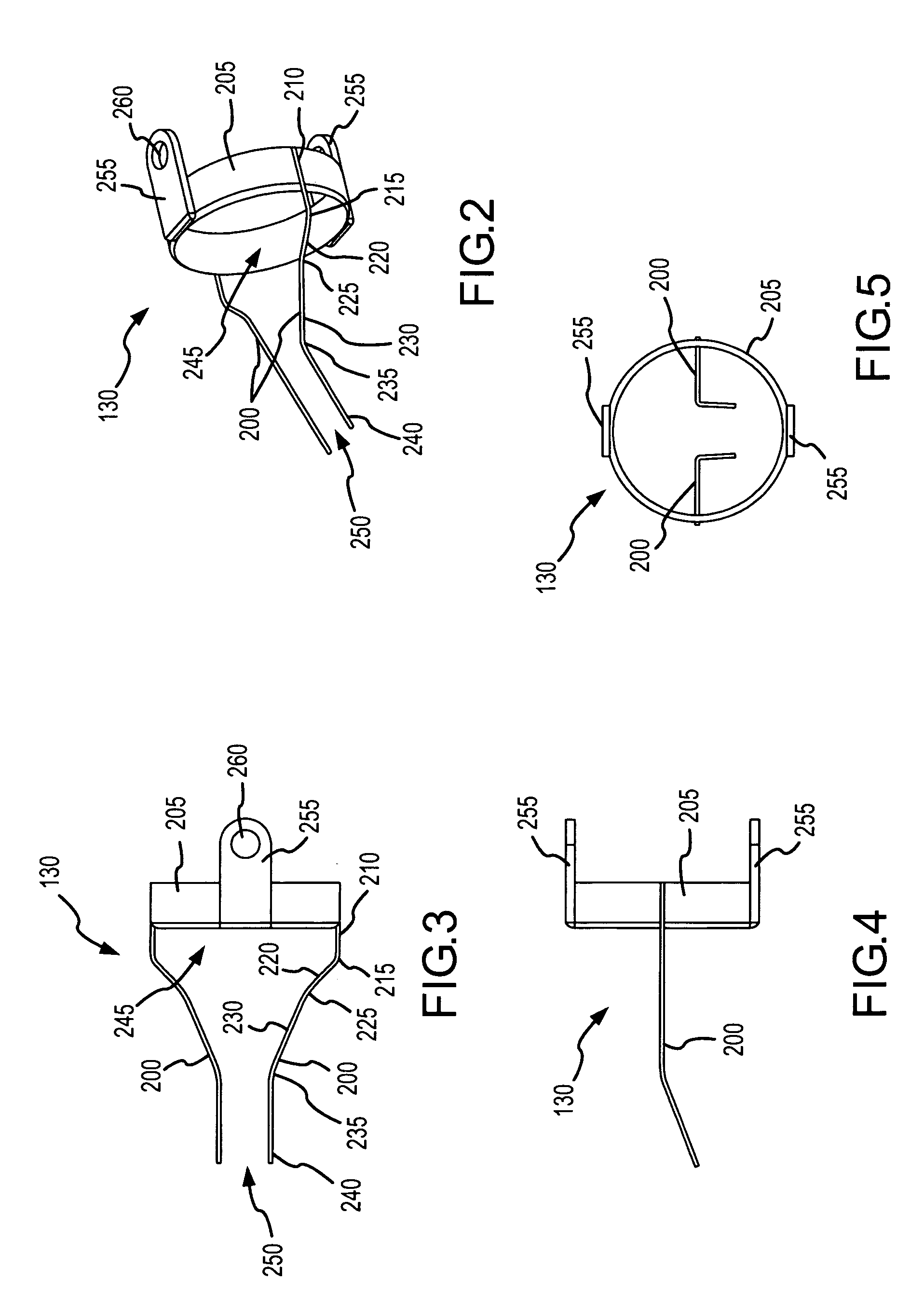
[0039]One particular configuration of the invention involves a charged particle guide coupled with a secondary electron detector of a FIB tool. The charged particle guide, in one particular configuration, includes a pair of wires extending from secondary ...


PUM


Abstract

A charged particle guide adapted to be coupled with a charged particle detector, such as a secondary electron detector. The charged particle guide, in one example, comprising two wires extending from the charged particle detector toward a source of charged particles, such as secondary electrons emitted from an IC upon application of a focused ion beam. Upon application of a bias voltage, the charged particle guide introduces a collecting electric field that attracts charged particles and directs the charged particles to the charged particles detector.

Description

FIELD OF THE INVENTION[0001]The present invention involves a charged particle guide, and more particularly involves a charged particle guide for enhancing collection of secondary electrons in a focused ion beam tool.BACKGROUND[0002]Charged particle beam systems, such as focused ion beam (“FIB”) systems, have found many applications in various areas of science and industry. For example, in the semiconductor industry, FIB systems are used for integrated circuit (“IC”) probe point creation, circuit editing, failure analysis, and numerous other applications. A FIB tool typically includes a particle beam production column designed to focus an ion beam onto the IC at the place intended for the desired intervention. Such a column typically comprises a source of ions, such as Ga+, produced from liquid metal. The Ga+ is used to form the ion beam, which is focused on the IC by a focusing device comprising a certain number of electrodes operating at determined potentials so as to form an elect...

Claims


Application Information

Patent Timeline
Patent Type & Authority Patents(United States)
IPC IPC(8): H01J37/244H01J37/28
CPCH01J37/244H01J37/3005H01J2237/2448
Inventor WANG, QINSONG STEVEMIAU, TZONG TSONGLUNDQUIST, THEODORE R.
Owner DCG SYST
Why Eureka
Try Eureka