
Apparatus and Method for Inspecting Samples

a sample and apparatus technology, applied in the field of apparatus and methods for inspecting samples, can solve the problems of inability to observe the reaction of living cells to a stimulus, exorbitantly long observation time, and inability to achieve high throughput observation, so as to facilitate the maintenance of the apparatus and reduce the cost

Inactive Publication Date: 2010-09-30
JEOL LTD
View PDF6 Cites 51 Cited by
  • Summary
  • Abstract
  • Description
  • Claims
  • Application Information

AI Technical Summary

Benefits of technology

[0019]It is an object of the present invention to provide apparatus and method for inspecting a sample, the apparatus having a shutter capable of partially partitioning the inside of a vacuum chamber. The apparatus can detect a tertiary signal produced from the shutter when a secondary beam emanating from the sample reaches the shutter. An image of the specimen is obtained based on the detected tertiary signal. In consequence, the shutter is closed quickly. This facilitates maintaining the apparatus. In addition, the shutter can be fabricated at lower cost.
[0022]Another inspection method, according to the present invention, includes the steps of: holding a sample on a first surface of a film; reducing the pressure of an ambient in contact with a second surface of the film; irradiating the sample with a primary beam using the primary beam irradiation column from a side of the second surface of the film via the film; causing a secondary beam produced from the sample in response to the primary beam irradiation to be directed at a shutter that partially partitions the space between the film and the primary beam irradiation column; and detecting a tertiary signal produced concomitantly from the shutter.
[0025]The present invention pertains to an inspection apparatus having: a film including a first surface on which a sample is to be held; a vacuum chamber for reducing the pressure in an ambient in contact with a second surface of the film; primary beam irradiation column for irradiating the sample held on the film with a primary beam via the film, the primary beam irradiation column being connected with the vacuum chamber; a shutter located between the film and the primary beam irradiation column in the vacuum chamber and configured to pass the primary beam coming from the primary beam irradiation column, the shutter partially partitioning the space between the film and the primary beam irradiation column in the vacuum chamber; and signal detector for detecting a tertiary signal produced from the shutter when a secondary beam emanating from the sample in response to the primary beam passes through the film and reaches the shutter. The present invention also pertains to an inspection method using this inspection apparatus. The apparatus can be maintained easily.
[0026]That is, the shutter producing the tertiary signal acts also to partially partition off the space between the film and the primary beam irradiation column within the vacuum chamber. Consequently, if the film is broken and the sample held on the film flows into the vacuum chamber, the shutter quickly partitions the primary beam irradiation column and the film from each other. This can prevent the primary beam irradiation column from being contaminated with the sample. In this case, the shutter becomes contaminated, but it may be cleaned or replaced.
[0027]Because the shutter is simple in structure, the cost can be reduced. In the past, whenever the film was damaged, the inside of the apparatus needed to be cleaned. The present invention facilitates or dispenses with the cleaning (using part replacement).

Problems solved by technology

It has thus been nearly impossible to observe reactions of living cells to a stimulus.
Accordingly, an exorbitantly long time has been required to observe the sample.
It has been impossible to achieve high throughput observations.
However, with this technique, the sample is sealed in the closed space and so it has been impossible to give a stimulus (such as application of a voltage or administration of a test reagent) to cells using a manipulator or pipette.
Therefore, as the culture medium evaporates, the salinity concentration rises, making it difficult to culture cells.
Where the cells should be observed or inspected in vivo, there arises a problem.
However, if the film is destroyed either by stimulation induced by an electron beam or by a mechanical stimulus, a new problem is created.
That is, the culture medium flows out in quantity, thus contaminating the inside of the apparatus.
The resolution of an optical microscope is not high enough to observe very tiny regions of biological cells.
Therefore, there is the problem that it has been impossible to observe the state of the specimen immediately after a stimulus is given (e.g., application of a voltage or administration of a test reagent) from the outside to the specimen using a manipulator or pipette.
Furthermore, the internal capacity of the sample capsule is small.
Consequently, when moisture evaporates and the salinity concentration rises, it is difficult to culture cells for a long time inside the sample capsule.
Hence, there are problems in observing cells for a long time.
However, in the SEM of this structure, the film may be destroyed due to the difference in pressure between the upper and lower surfaces of the film.
Therefore, it takes a long time to achieve this closing operation, thus presenting a problem.

Method used


Image

  • Apparatus and Method for Inspecting Samples
  • Apparatus and Method for Inspecting Samples
  • Apparatus and Method for Inspecting Samples

Examples


Embodiment Construction

[0035]Apparatus and method for inspection in accordance with the present invention are hereinafter described with reference to the drawings.

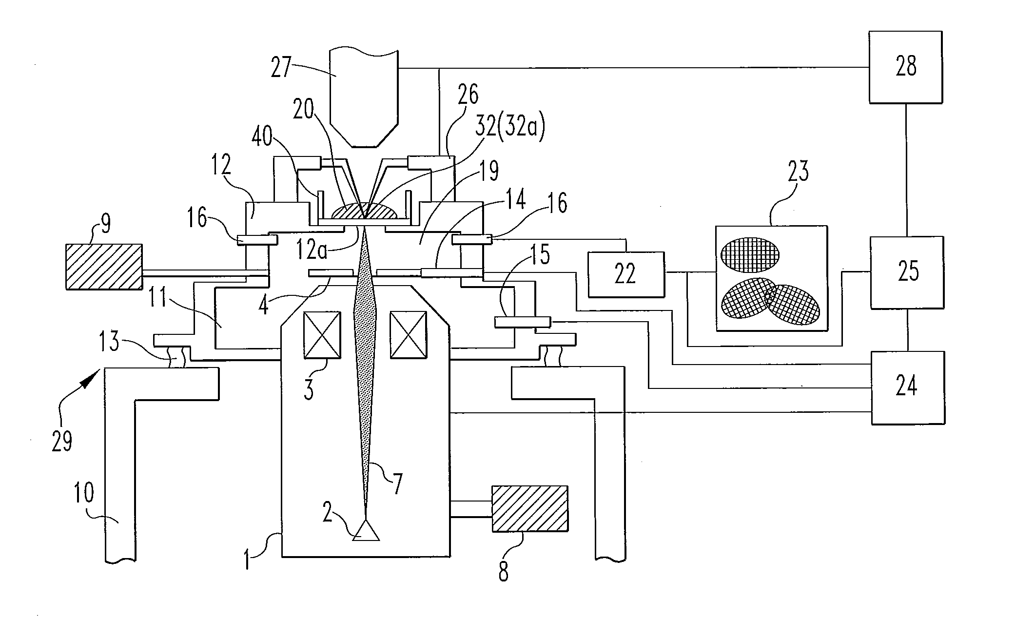
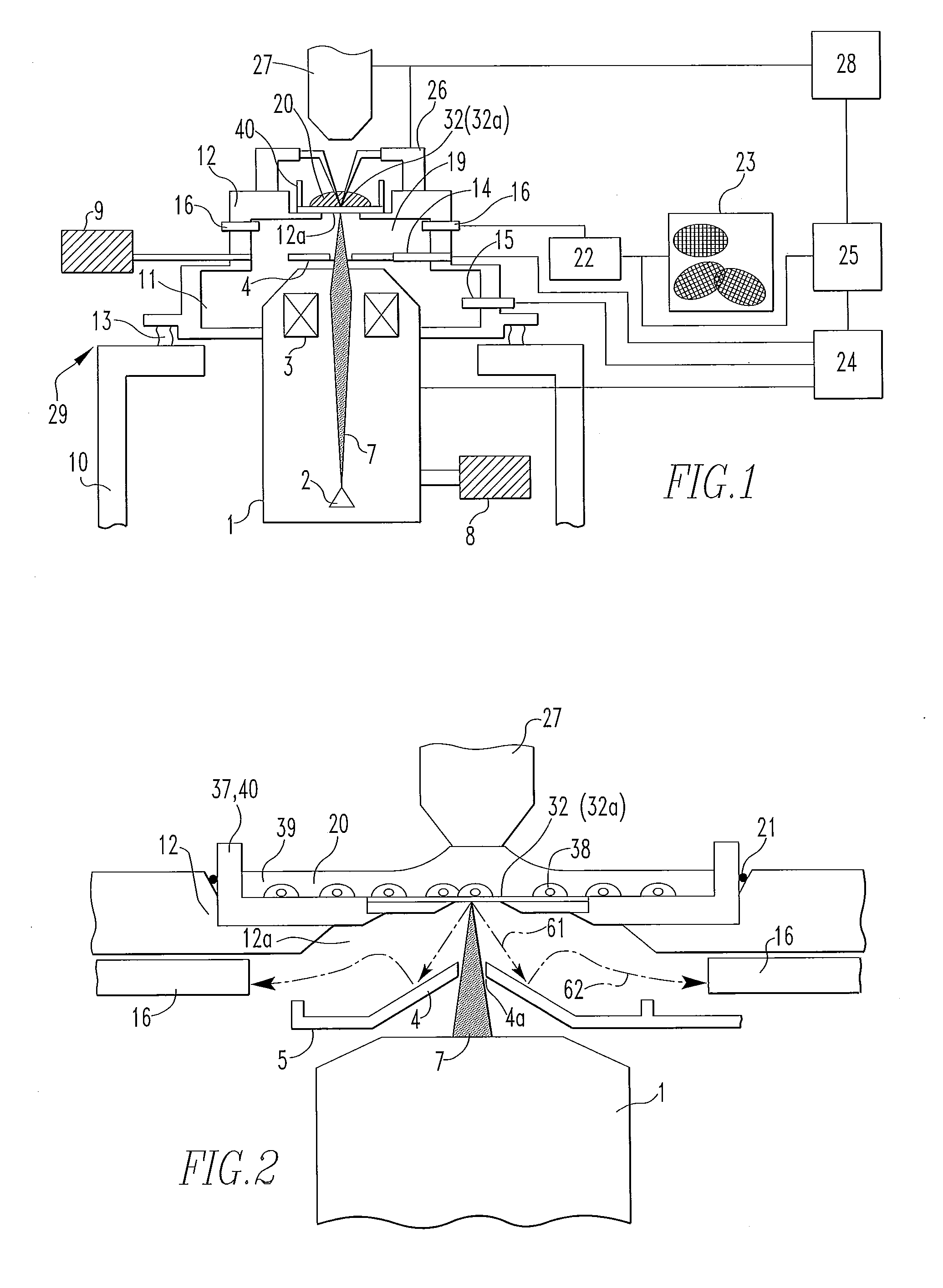
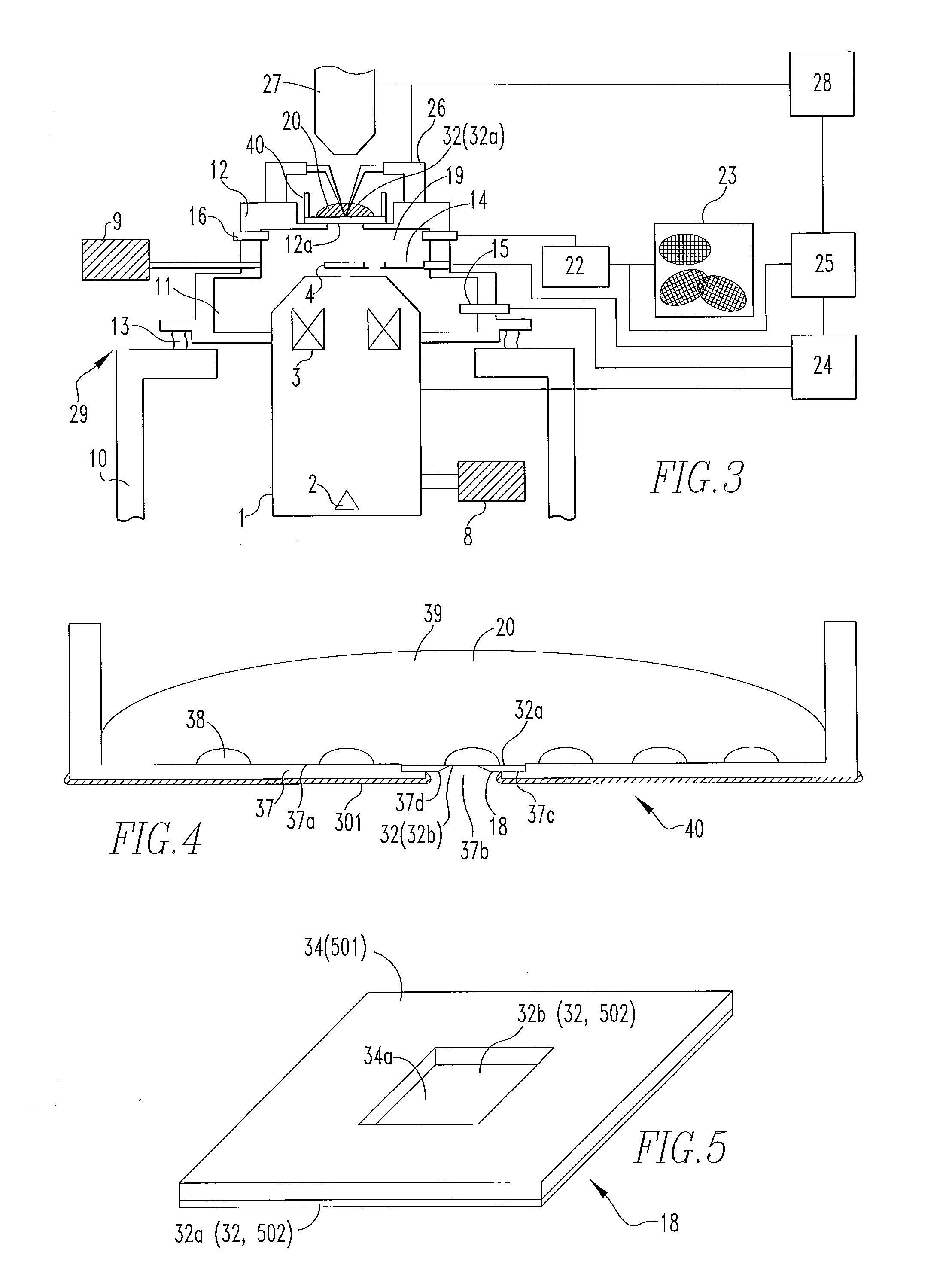
[0036]FIG. 1 is a schematic block diagram showing a first embodiment of a sample inspection apparatus, according to the present invention. The apparatus consists chiefly of an optical microscope 27, a manipulator 26, and an electron beam apparatus section 29 located under a sample holder 40.

[0037]Referring to FIG. 1, a primary beam irradiation column comprises an electron gun 2 forming an electron source. The gun 2 emits an accelerated electron beam (charged-particle beam) 7 upwardly, the beam being a primary beam. The beam 7 is focused by a condenser lens (objective lens) 3.

[0038]The focused electron beam 7 is directed at a liquid sample 20 via a sample-holding film 32 (described later) formed on the sample holder 40. The sample 20 is held on the sample holder 40. In the present embodiment, the liquid sample 20 includes biological cells 38 (to ...


PUM


Abstract

An inspection apparatus and method capable of well observing or inspecting a specimen contained in a liquid. The inspection apparatus has a film including first and second surfaces. Furthermore, the apparatus has a vacuum chamber for reducing the pressure in the ambient in contact with the second surface of the film, primary beam irradiation column connected with the vacuum chamber, and a shutter for partially partitioning the space between the film and the primary beam irradiation column within the vacuum chamber. A liquid sample is held on the first surface of the film. The primary beam irradiation column irradiates the sample. Backscattered electrons (a secondary beam) produced from the sample by the primary beam irradiation are directed at the shutter, producing secondary electrons (a tertiary signal).

Description

BACKGROUND OF THE INVENTION[0001]1. Field of the Invention[0002]The present invention relates to apparatus and method permitting good observation or inspection either of a specimen contained in a liquid or of a sample consisting of biological cells which have been cultured and are present in a liquid culture medium.[0003]2. Description of Related Art[0004]Living organisms are multi-cellular and develop diseases if information cannot be transmitted normally among cells or if viruses or chemical substances cling to cells. For this reason, in the fields of molecular biology and pharmaceutics, research is conducted by peeling off cells from a living organism, cultivating the cells on a laboratory dish, giving a stimulus, such as electricity, chemical substance, or medicine to the cells, and observing the resulting reaction on the cellular level. In the past, optical microscopes have been used for such observations. Manipulators or pipettes have been employed to give stimuli to cells. Fr...

Claims


Application Information

Patent Timeline
IPC IPC(8): G01N23/22H01J37/26
CPCH01J37/20H01J37/244H01J2237/24475H01J2237/2004H01J2237/2443H01J2237/2003
Inventor NISHIYAMA, HIDETOSHIKOIZUMI, MITSURUSUGA, MITSUO
Owner JEOL LTD
Learn More