Check patentability & draft patents in minutes with Patsnap Eureka AI!

Two arm shoulder joint mechanism of two arm robot and two leg hip joint mechanism of two leg walking robot

A shoulder joint and hip joint technology is applied in the field of the double-arm shoulder joint mechanism of the double-arm robot and the double-leg hip joint mechanism of the biped walking robot, and can solve the problems of increasing the degree of freedom and the like

Inactive Publication Date: 2006-09-13
THE UNIV OF TOKYO
View PDF0 Cites 1 Cited by
  • Summary
  • Abstract
  • Description
  • Claims
  • Application Information

AI Technical Summary

Problems solved by technology

However, increased degrees of freedom are undesirable relative to humanoid robots due to the requirement to reduce weight and size

Method used


Image

  • Two arm shoulder joint mechanism of two arm robot and two leg hip joint mechanism of two leg walking robot
  • Two arm shoulder joint mechanism of two arm robot and two leg hip joint mechanism of two leg walking robot
  • Two arm shoulder joint mechanism of two arm robot and two leg hip joint mechanism of two leg walking robot

Examples


Embodiment Construction

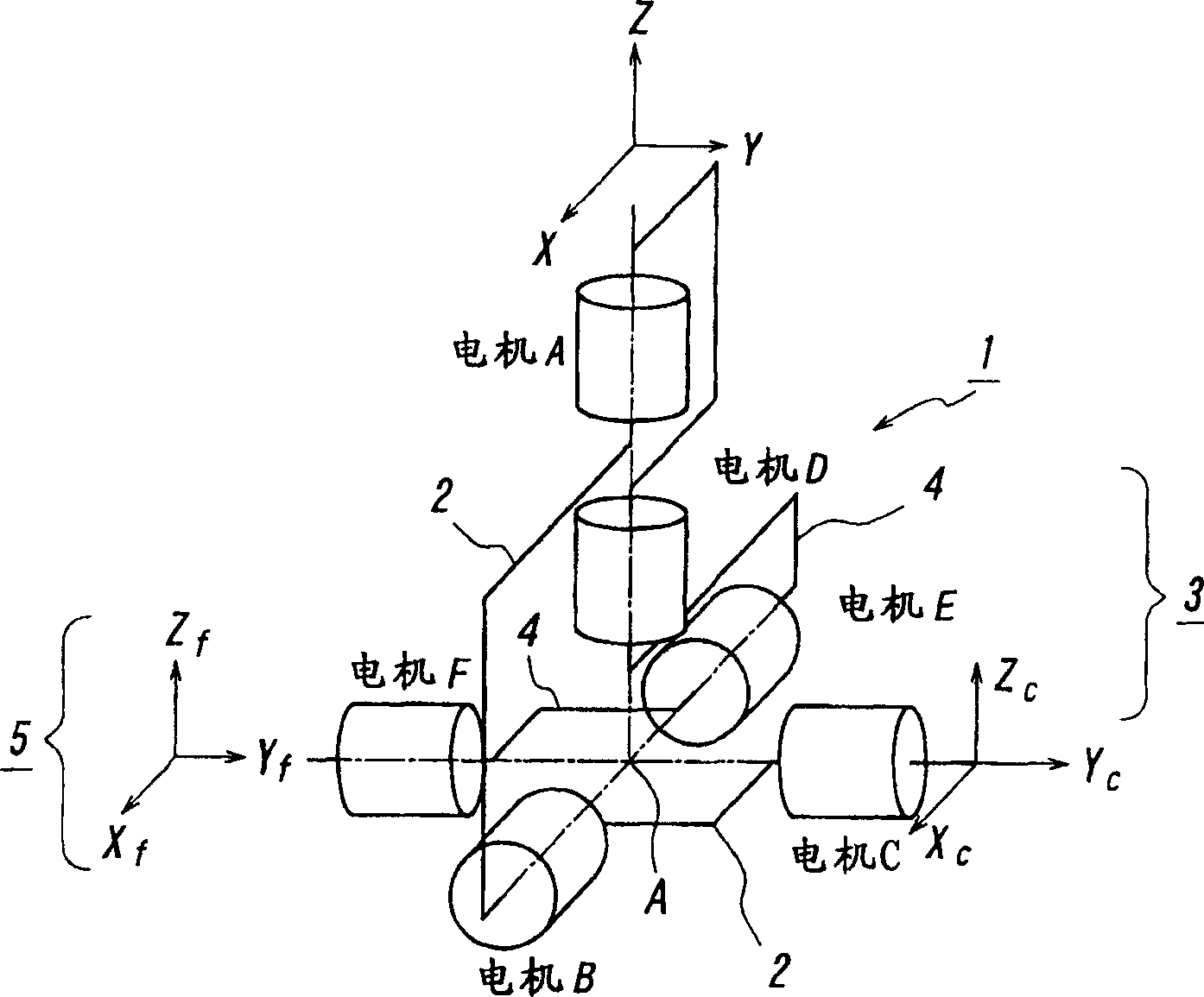
[0027] figure 1 It is a schematic diagram showing an embodiment of a double ball joint used in a double-arm shoulder joint mechanism and a double-leg hip joint mechanism according to the present invention. exist figure 1 In the illustrated embodiment, a double ball joint 1 comprises: a first ball joint 3 consisting of motors A, B and C used as actuators and a link used to connect the respective axes of rotation of said motors 2; and a second ball joint 5 consisting of motors D, E, and F used as actuators and a link 4 used to connect the respective rotating shafts of said motors. Also, in the double ball joint 1, the rotation centers of the first ball joint 3 and the second ball joint 5 are connected to a point A. As shown in FIG. In the above institutions, also in the Figure 8 In the mechanism shown, a coordinate system XcYcZc is established for motor C, and a coordinate system XfYfZf is established for motor F, which coordinate systems can express arbitrary postures ind...


PUM


Abstract

As a double-arm shoulder joint mechanism of a double-arm robot and a both-legs hip joint mechanism of a biped-walk robot, use is made of a double spherical joint having a construction such that joint rotation axes of 6 DOF are intersected at one point. As the double-arm shoulder joint mechanism of the double-arm robot, arms are connected respectively to a first spherical joint and a second spherical joint of the double spherical joint. As the both-legs hip joint mechanism of the biped-walk robot, legs are connected respectively to the first spherical joint and the second spherical joint of the double spherical joint.

Description

technical field [0001] The invention relates to a double-arm shoulder joint mechanism of a double-arm robot and a double-leg hip joint mechanism of a biped walking robot, and also relates to a shoulder joint mechanism and a hip joint mechanism of a humanoid robot using the above-mentioned mechanism. Background technique [0002] Usually, such as Figure 6 As shown, the dual-arm robot is used for industrial purposes, and is realized by two independent robots 52-1, 52-2 arranged on a base 51. The working space that the arms of robots 52-1, 52-2 can reach simultaneously is defined by Figure 7 The shaded portion shown indicates a view from above. The workspace in which the robots 52-1, 52-2 cooperate with each other is smaller than the respective arm lengths of the robots 52-1, 52-2. As a method of extending the working space, it is conceivable to provide an actuator for rotating the entire base 51 . However, this method increases degrees of freedom (hereinafter, sometimes a...

Claims


Application Information

Patent Timeline
IPC IPC(8): B25J17/00A63H11/00A63H11/18B25J5/00B25J17/02
CPCB25J17/0275Y10T74/20329B25J17/00
Inventor 中村仁彦岡田昌史篠原彻也
Owner THE UNIV OF TOKYO
Features
  • R&D
  • Intellectual Property
  • Life Sciences
  • Materials
  • Tech Scout
  • Unparalleled Data Quality
  • Higher Quality Content
  • 60% Fewer Hallucinations
Learn More