
Optical scanning device

An optical scanning device and optical recording technology, applied in the direction of optics, optical components, optical recording heads, etc., can solve the problems of not saving cost, scrapping the transmission device, not saving space, etc., and achieve the effect of large manufacturing tolerance and cost saving

Inactive Publication Date: 2006-09-20
KONINKLIJKE PHILIPS ELECTRONICS NV
View PDF4 Cites 0 Cited by
  • Summary
  • Abstract
  • Description
  • Claims
  • Application Information

AI Technical Summary

Problems solved by technology

However, the first method needs to utilize an additional part to support the first, second and third objective lenses, thus making the objective lens group relatively expensive and bulky, which cannot save space
The disadvantage of the second method is that once the objective lens is assembled in the transmission and fixed (ie glued) therein, then the scrapping of the objective lens group for testing reasons will lead to the scrapping of the transmission, which is not cost-effective

Method used


Image

  • Optical scanning device
  • Optical scanning device
  • Optical scanning device

Examples


Embodiment Construction

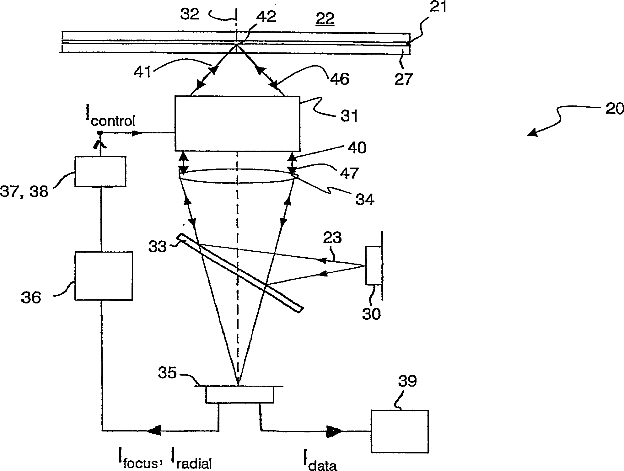
[0027] FIG. 3A shows an optical scanning device 20 according to the invention, which device is suitable for scanning a first information layer 21 of a first optical record carrier 22 with a first radiation beam 23 . FIG. 3B shows the same optical scanning device 20 suitable for scanning the second information layer 24 of the second optical record carrier 25 with the second radiation beam 26 . As described below, FIGS. 3A and 3B correspond to the first mode and the second mode, respectively.

[0028] Hereinafter, the first mode refers to a mode of operation of the optical scanning device 20 for having a first numerical aperture NA 1 The radiation beam scans the information layer 21. The numerical aperture NA 1 Suitable for scanning a first type of optical record carrier (eg so called DVR format) having a first information density. The second mode refers to a mode of operation of the optical scanning device 20, which is used to have a ratio numerical aperture NA 1 Small seco...


PUM


Abstract

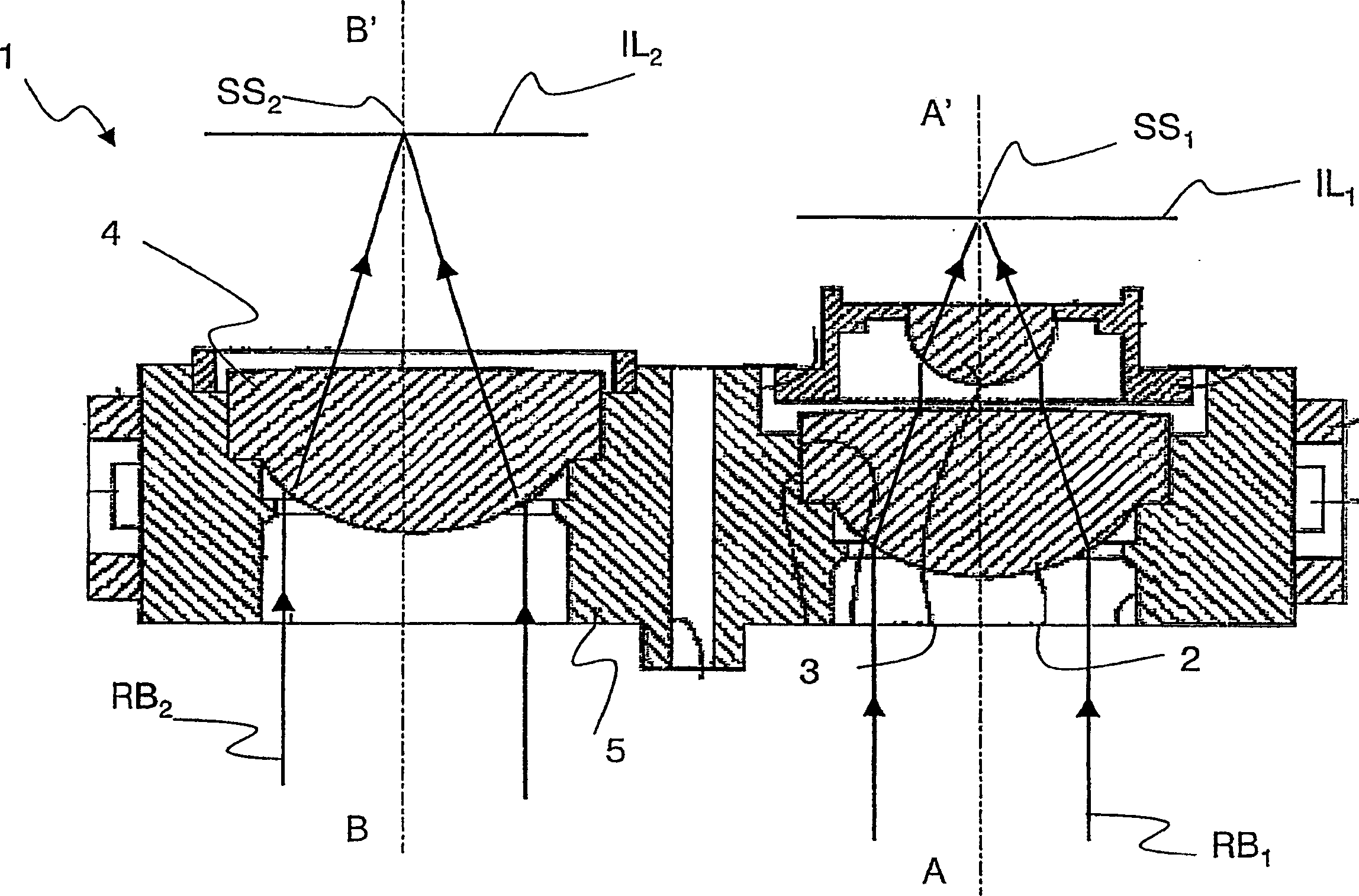
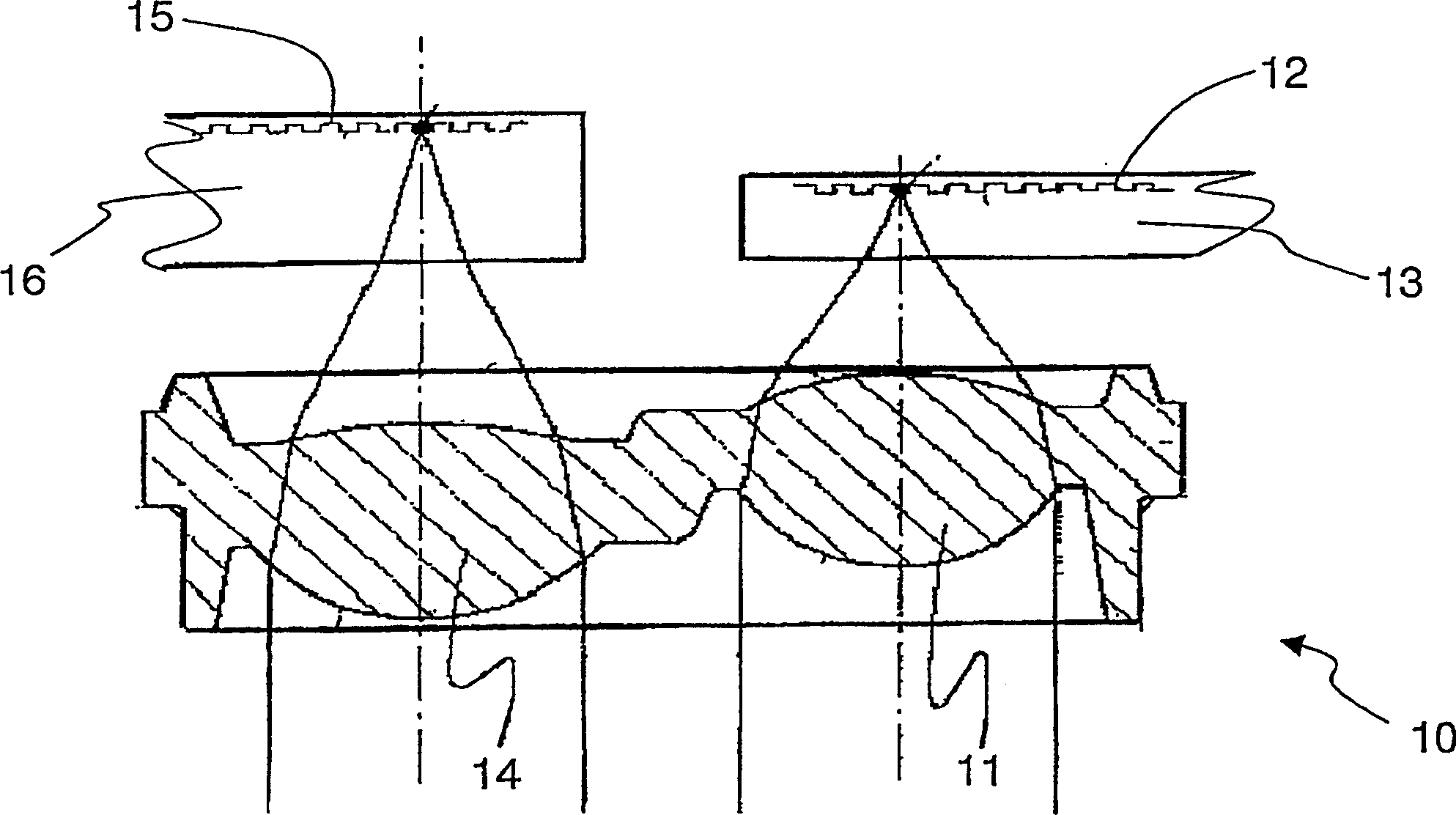
An optical scanning device is used for scanning first and second information layers with first and second radiation beams. The device includes a radiation source and an objective lens assembly (31). The lens assembly includes a doublet-lens system (61, 62) including a first objective lens (61) with a first cross-section having a first diameter (d1) and a second objective lens (62) with a second cross-section having a second, smaller diameter (d2). The first and second lenses are arranged for transforming the first radiation beam to a first focused radiation beam having a first numerical aperture. The objective lens assembly further includes a third objective lens (63) for transforming the second radiation beam to a second focused radiation beam having a second, smaller numerical aperture. The second and third objective lenses are integrally formed in one body (64).

Description

technical field [0001] The invention relates to an optical scanning device for scanning a first information layer in a first optical record carrier with a first radiation beam and a second information layer in a second optical record carrier with a second radiation beam, The device comprises a radiation source for providing said first and second radiation beams and an objective lens group comprising: (1) a double lens system comprising a first objective lens and a second objective lens, wherein the first objective lens is laterally The cross-section has a first diameter, and the cross-section of the second objective lens has a second, smaller diameter, the first and second objective lenses are arranged for converting the first radiation beam into a first radiation beam having a first numerical aperture. a focused radiation beam to form a first scanning spot at the location of said first information layer, and (2) a third objective lens for converting said second radiation beam...

Claims


Application Information

Patent Timeline
IPC IPC(8): G11B7/135G11B7/125G02B13/00G02B13/18G02B26/00G11B7/00G11B7/09G11B7/22
CPCG11B7/13922G11B7/093G11B7/1275G11B7/1374G11B2007/0006G11B2007/13727G02B13/00
Inventor B·H·W·亨德里克斯
Owner KONINKLIJKE PHILIPS ELECTRONICS NV
Learn More